Advertisement
FUTURE KIT
R
HIGH QUALITY ELECTRONIC KITS
FUTURE KIT
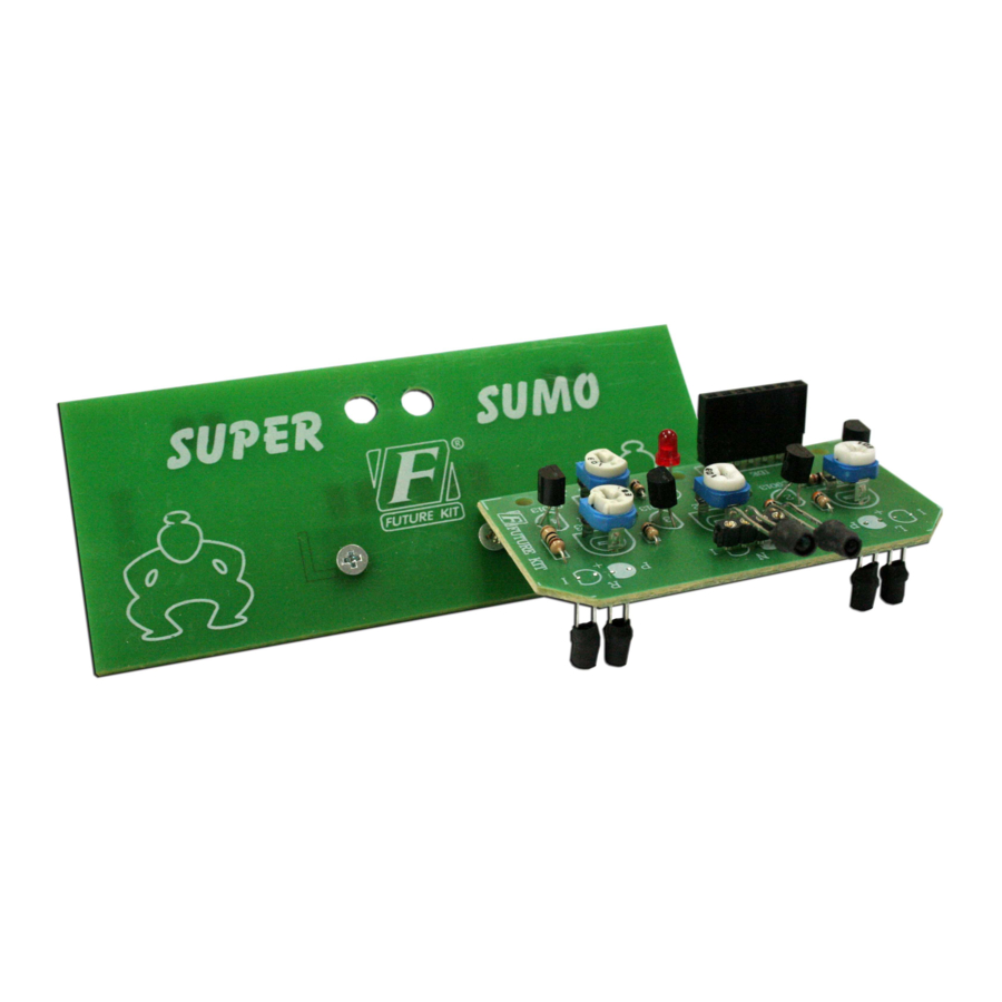
AVR1 SUPER SUMO ROBOT
CODE 1109
This super sumo can be controlled to attack or retreat and
ready for battle with opponent. This robot is using the AVR
microcontroller, so the user can re-program into IC for getting
new applications.
Technical Specifications:
- Power supply : 2 AA batteries (not included).
- Consumption : 80mA.
- PCB dimensions : 2.54 x 1.18 in. (sensor board)
2.54 x 2.70 in. (control board)
(1) ROBOT CONTROL CIRCUIT
How To Work:
The circuit is composed of 2 major parts, sensor board and
control board, as shown in Fig. 1.
Sensor board have 3 sets, in set as transmitter and receiver
of infrared light. Transmitter part is consist TR4 and LED
INF. VR4 is used for adjust the level of infrared light. Receiver
part, when photo-transistor received infrared light from LED
INF, causing voltage being passed through. The more reflected
light will lessen the internal resistance and give bigger passing
through voltage. Less reflected light will enlarge the internal
resistance and give less passing through voltage. TR1 to TR3
will work when the photo-transistor received infrared light.
Control board, at the heart of the circuit is the AVR
microcontroller IC1. When below photo-transistor is not
receiving infrared light (white ground), TR1 to TR3 are not
working. IC1 will send the voltage to pin 12 and pin 15,
causing both motor is running forward. If some below photo-
transistor received infrared light (black ground), motor is
running backward. For center sensor, when sensor detects the
HIGH QUALITY ELECTRONIC KIT SET FOR HOBBY & EDUCATION
object, IC1 will send the voltage pin 9 and pin 14, causing
motor is rotate faster. IDE port is used for connect AVR
programmer.
Circuit Assembling:
The PCB will be divided into two boards, AVR1-1 for
circuit controlling and Body set for body, motor gear, wheel
and battery holder assembling.
The AVR1-1 circuit assembling has been shown in Fig 2. It
is recommended to assemble the circuit starting with a less
height component i.e. diodes, resistor, electrolytic capacitors
and transistors etc. Be careful while assembling and check for
the matching of PCB poles and components before soldering as
shown in Fig 3. For IDE port, press the pin of IDE port to be
level with the black plastic before soldering. Use a max. 40W
solder and soldering tin with a tin and lead ratio of 60/40
together with a joint solution inside. Recheck the assembled
circuit for your own confidence. Better use a lead sucker or a
lead wire absorber in case of component misplacing to protect
PCB from damage.
The Body set is to be assembled as shown in the next page.
Testing:
When the two circuit boards have been completely
assembled. Insert four AA batteries into the battery holder.
Then adjust VR1 to VR4 to the middle side and slide switch
SW to "on" position. LED at sensor board is lighted on. Lay
down the assembled robot on the test paper. Robot is running
inside the black frame. The robot will backward and turn
when below sensor detecting the black line. But front sensor
detects the any object, the robot will run forward and running
up the speed to bump.
VR1 to VR3 will act as sensitivity of photo-transistor.
Adjust the left hand side for decreasing sensitivity and to the
right hand side for increasing sensitivity. VR4 will act as level
of infrared light.
SW1 is used for set the speed of robot. When you want to
setting the speed, slide switch SW to "off" position then push
and hold SW1. Slide SW to "on" position. Seeing LED at
control board. LED will chasing step by step. LED1 is slowly
speed and LED4 is higher speed.
µ
F
µ
F
µ
F
µ
F
Figure 1. AVR1 Super Sumo Robot Circuit
Figure 2. AVR1-1 and SENSOR1-1 Circuit Board Assembling
Photo-Transistor
AND LED Infrared
COPPER
LAYER
IDE port
IDE port
IDE port
(Connect with programmer)
SENSOR BOARD
RESISTOR 1/8W
R1
500Ω - green-black-brown-gold
R2,R5,R7,R9 1kΩ
R4,R6,R8
3kΩ
µ
F
RESISTOR 1/4W
R3
10Ω
TRIMMER POTENTIOMETERS
VR1-VR4
=
CONTROL BOARD
RESISTOR 1/4W
R1,R2,R4
R3
R5,R6,R12,R14,R19
R7-R11,R13,R15-R18
Troubleshooting:
As the circuit has only a few components, the main
cause of troubles will come from component
misplacing and defaulted soldering. When found out
that the circuit does not work, check for the proper
component placings and various soldering points.
SENSOR2-1
N
P
I
+
C9013
VR1
L
2
3
1K
VR2
VR3
N
R
1K
1K
K
1
C9013
LED
C9013
500
A
VR4 I
+
F
µ
C9012
47
0.1
1K
1
2
C9013
500
3
4
500
A
LED
1
1K
K
LED
1K
2
5
A
500
C9013
C9013
C9013
500
K
A
LED
1K
3
7
8
1K
LED
K
SW1
500
4
A
10
C9013
ON
G
AVR1-1
Figure 3. Components Installing
- brown-black-red-gold
- orange-black-red-gold
- brown-black-black-gold
POTENTIOMETER
10kΩ or 103
150Ω
- brown-green-brown-gold
50Ω
- green-black-black-gold
LED Infrared
1kΩ
- brown-black-red-gold
(Blue Clear)
500Ω
- green-black-brown-gold
A
LED I NF
I
K
A
LED
http://www.futurekit.com
Photo-Transistor
AND LED Infrared
COPPER
LAYER
4
C9013
IDE port
NOTE : For all IDE port to
6
insert the PC-board and solder
C9012
without trim leg.
9
+
IDE port
OFF
ELECTROLYTIC
RESISTOR
CAPACITOR
+
R .....
Ω
C .....
F
µ
+
TRIMMER
+
C
C
!
Watch the polarity
VR .....K
Ω
TRANSISTOR
1
3
C
E
2
B
B
C
NPN
E
PNP
Photo-Transistor
K
(Black)
I
PH OTO T R
P
P
RED LED
D
DIODE
A
K
A
K
A
K
A
LED
K
Advertisement
Table of Contents

Related Manuals for FUTURE KIT AVR1 SUPER SUMO ROBOT


Summary of Contents for FUTURE KIT AVR1 SUPER SUMO ROBOT
- Page 1 When found out that the circuit does not work, check for the proper component placings and various soldering points. Figure 1. AVR1 Super Sumo Robot Circuit http://www.futurekit.com HIGH QUALITY ELECTRONIC KIT SET FOR HOBBY & EDUCATION...
- Page 2 (2) ROBOT BODY Assembling Steps of the Body set. Screw 2x1/4 Mount BR002-1 PC-board into Screw 4x1/4 body robot and secure them Mini Caster Flat head nut with two #2 x 1/4" screws. 2.5x10 and NUT M2.5 Fix a mini caster wheel set to the Body set with using a 12 mm.
- Page 3 FUTURE KIT FUTURE KIT...
Need help?
Do you have a question about the AVR1 SUPER SUMO ROBOT and is the answer not in the manual?
Questions and answers