Sign In
Upload
Download
Table of Contents
Contents
Add to my manuals
Delete from my manuals
Share
URL of this page:
HTML Link:
Bookmark this page
Add
Manual will be automatically added to "My Manuals"
Print this page
×
Bookmark added
×
Added to my manuals
Manuals
Brands
BRS Manuals
Measuring Instruments
BIM1
Instruction manual
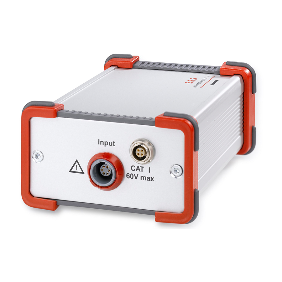
BRS BIM1 Instruction Manual
Battery impedance meters
Hide thumbs
1
2
3
Table Of Contents
4
5
6
7
8
9
10
11
12
13
14
15
16
17
18
19
20
21
22
23
24
25
26
27
28
29
30
31
32
33
34
35
36
page
of
36
Go
/
36
Contents
Table of Contents
Bookmarks
Table of Contents
Table of Contents
1 Overview
Short Description
Versions
Evaluation Functions
Selecting Languages
2 Operating Preparations
Unpacking
Installing the Programs
Positioning of the Instrument
Connecting the Measurement Cable for Impedance and Voltage
Connecting the Measurement Cable for Temperature or Current (BIM2/3)
Connecting the Digital Inputs/Outputs
Connecting the Test Item
3 Applications
4 Measurement Functions
Functional Principle of the Impedance Measurement
Overview
Settings
Battery Discharge During Extended Use
5 Operation
Measurement Function at Single Frequency
Measurement Function for Spectral Measurement
Measurement Function Capacity Test (BTC1 Only)
Evaluation Function Tolerance Test
Evaluation Function Diagnosis
Measuring and Monitoring Voltage
Temperature and Current Measurements (BIM2, BTC1)
Single Measurements
Instrument Configuration
6 Data Export
Data Export Via Text File (Log File)
Data Export Via Csv Files
7 Remote Control
8 Maintenance
Cleaning
Firmware Updates
Recalibration
Help
9 RS232 Communication
10 Technical Data
11 Appendix
Recommendations for Cable Running
Recommendations for Selecting Frequencies
Advertisement
Quick Links
1
Short Description
Download this manual
BIM1 / BIM2 / BTC1 / BIM300
Battery Impedance Meters
Instruction manual
Table of
Contents
Previous
Page
Next
Page
1
2
3
4
5
Advertisement
Table of Contents
Need help?
Do you have a question about the BIM1 and is the answer not in the manual?
Ask a question
Questions and answers
Related Manuals for BRS BIM1
Measuring Instruments BRS BIM2 Instruction Manual
Battery impedance meters (36 pages)
This manual is also suitable for:
Bim2
Btc1
Bim300
Table of Contents
Print
Rename the bookmark
Delete bookmark?
Delete from my manuals?
Login
Sign In
OR
Sign in with Facebook
Sign in with Google
Upload manual
Upload from disk
Upload from URL


Need help?
Do you have a question about the BIM1 and is the answer not in the manual?
Questions and answers