
Summary of Contents for Caen ELS REGUL8OR
- Page 1 REGUL8OR – User’s Manual REGUL8OR Digital High-Performance Programmable Power Supply Controller User’s Manual All Rights Reserved © CAEN ELS s.r.l. Rev. 1.2 – May 2021...
- Page 2 REGUL8OR – User’s Manual This product is compliant. CAEN ELS s.r.l. in AREA Science Park S.S. 14 km 163,5 loc. Basovizza – 34149 Trieste (TS) Italy Mail: info@caenels.com Web: www.caenels.com Registered office: via Vetraia 11 – 55049 Viareggio (LU) - Italy...
- Page 3 REGUL8OR – User’s Manual User’s Manual – Models – Options – Custom Models This manual covers the following standard REGUL8OR models: • REGUL8OR • REGUL8OR-PWM For technical assistance please refer to the following contact: CAEN ELS S.R.L. SS14 km 163,5 34149 loc.
-
Page 4: Table Of Contents
REGUL8OR – User’s Manual Table Of Contents INTRODUCTION ....................10 REGUL8OR O ................10 VERVIEW REGUL8OR ................13 AT A GLANCE DCCT – Direct Current Transducer ............15 Digital Control Loop ................15 ..................17 PERATION ODES Regulation Mode ..................17 Control Mode ................... - Page 5 REGUL8OR – User’s Manual 2.15 .................. 46 ATING ONNECTORS LOCAL CONTROL ..................47 ..................47 AVIGATION WITCH ......................47 ISPLAY Power-up ....................48 Home Screen .................... 49 Menu Page ....................51 Control Page ..................52 Config Page ..................53 Advanced Page ................. 54 MECHANICAL DIMENSIONS ...............
- Page 6 REGUL8OR – User’s Manual Document Revisions Revision Date Comment October 2 , 2020 First Release October 7 , 2020 Corrections made on several sections May 21 , 2021 Updated Local Control Section...
- Page 7 REGUL8OR – User’s Manual Safety information The following table shows the general environmental requirements for a correct operation of instruments referred in this User’s Manual: Environmental Conditions Requirements Environment Indore use Operating Temperature 0°C to 40°C Operating Humidity 20% to 80% RH (non-condensing)
- Page 8 Modules due to negligence on behalf of the User. It is strongly recommended to read thoroughly this User's Manual before any kind of operation. CAEN ELS s.r.l. reserves the right to change partially or entirely the contents of this Manual at any time and without giving any notice.
- Page 9 REGUL8OR – User’s Manual Disposal of the Product The product must never be dumped in the Municipal Waste. Please check your local regulations for disposal of electronics products. WARNING • Do not use this product in any manner not specified by the manufacturer.
-
Page 10: Introduction
Thanks to the GUI (Graphic User Interface), the control and configuration of the REGUL8OR is straightforward, while the several interfaces present on the rear panel of the module allow for a quick and easy connection to the external power supply adding several functionalities. - Page 11 (or voltage) desired. The REGUL8OR then closes the voltage and current loops and elaborates the values in a digital PID.
- Page 12 REGUL8OR – User’s Manual The REGUL8OR can be also monitored and controlled via a navigation switch and a graphic high-resolution color display featuring user-friendly menus. In addition to the standard Ethernet interface, it is possible to communicate with the unit using the SFP-ports on the front panel. This interface allows communicating with the unit using a proprietary protocol (packet structure with a very high update rate (more than 10 kHz) for fast applications.
-
Page 13: Regul8Or At A Glance
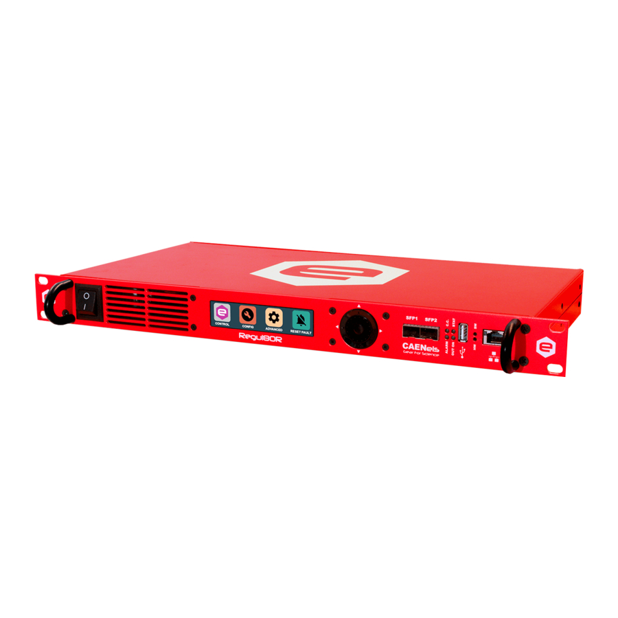
REGUL8OR – User’s Manual 1.2 REGUL8OR at a glance The REGUL8OR system is composed by a single 19-inch 1U crate. The unit and its I/O connections can be easily seen in Figure 2 (front view), Figure (rear view) and Figure (rear view with optical transmitters/receivers - optional). - Page 14 REGUL8OR – User’s Manual On the rear side of the unit are placed: AC power line input and all the connectors for the communication with other external devices. A brief description of the connector used are described in the Table 2.
-
Page 15: Dcct - Direct Current Transducer
Banana to sense the external voltage on the load Table 2: short description of the connectors on the rear panel of the REGUL8OR DCCT – Direct Current Transducer To achieve high performance in terms of stability and low noise in the current... - Page 16 REGUL8OR – User’s Manual Figure 5: schematic representation of the system The implementation of the digital control loop via the REGUL8OR adds flexibility to any analog existing system, allowing it to be tuned to any load condition easily and remotely.
-
Page 17: Operation Modes
Control Mode The REGUL8OR unit can be controlled in three main different ways that are hereafter listed: • LOCAL control: the unit can be controlled directly via the front panel color display and the navigation switch. -
Page 18: Update Mode
REGUL8OR – User’s Manual Update Mode The current or voltage setting of the unit can also be performed in four different modes: • NORMAL: the update of the set-point (current or voltage, depending on the operation mode – i.e. CC or CV respectively) is performed as soon as a new set-point is received via the remote, local or fast interfaces •... -
Page 19: External Interlocks And Status Signals
A description of the configuration of the external interlocks using the power supply commands is hereafter described. The REGUL8OR also presents 6 (six) output status signals that are divided into: • 2 (two) magnetic relays with the NO, NC and COMMON taps;... -
Page 20: Interlock Intervention Time
REGUL8OR – User’s Manual It is necessary to write on the advanced configuration parameters with the Web Interface or via standard power supply commands in order to configure the interlock state mask. Interlock Intervention Time The module also allows to setting the interlock intervention time (the time that an interlock signal needs to be at its activation level before tripping and thus generating a fault condition). -
Page 21: Trigger And Analog Control Inputs
REGUL8OR – User’s Manual 1.5 Trigger and Analog Control inputs The standard version of the REGUL8OR includes inputs for a trigger signal and for an analog control on the rear panel. A brief description of these features and their functionalities is presented hereafter. -
Page 22: Analog Control Input
(for the external unit) which is proportional to the input signal. This means that the REGUL8OR will regulate the output at -100 % for a –10 V analog input voltage, a 0% for a 0 V analog input voltage and a +100 % for a +10 V analog input voltage. - Page 23 REGUL8OR – User’s Manual Analog Control +100% +10V -10V -100% AN CTRL OUTPUT Figure 7: ANALOG CONTRL vs OUTPUT of the general-purpose power supply controlled Please note that the bandwidth of the analog control input is internally limited to approximately 25 kHz.
-
Page 24: External Sensors
REGUL8OR – User’s Manual 1.6 External Sensors The REGUL8OR is equipped with an input connector on the rear panel that allows users to connect different external sensors useful for sensing an external temperature or a magnetic field for example. Having two different voltage supplies (1.8 V and 3.3 V referred to chassis ground) for the external temperature sensor allows installing a variety of different temperature sensors. -
Page 25: Synchronization Of Multiple Units
Figure 9: schematic representation of a synchronization of multiple units 1.8 External SPI An isolated SPI interface is present on the rear panel of the REGUL8OR on an 8- pin connector. This 4-wire SPI allows interfacing external devices to the unit in order to match specific applications. -
Page 26: Output Connectors
REGUL8OR – User’s Manual Figure 10: schematic representation of a connection between the Regul8OR and a generic external device made with the SPI 1.9 Output Connectors The REGUL8OR has been designed to control an external power stage/programmable power supply with an analog output voltage or, in specific cases, an analog output current (to close a 4-20 mA loop). -
Page 27: Input Voltage And Current Connectors
REGUL8OR – User’s Manual 1.10 Input Voltage and Current connectors The output current and the output voltage are sensed by connectors placed on the device rear panel. The current is measured with a proprietary DCCT supplied and connected from/to a DSUB9 female connector. This cable is supplied together with the REGUL8OR unit. -
Page 28: Front Panel Indicators
REGUL8OR – User’s Manual 1.11 Front Panel Indicators The REGUL8OR has four (4) front panel LED indicators as shown in the following Figure 11 Figure 11: front panel indicators The front panel indicators and their behaviour are hereafter listed (clockwise starting from top-left): •... -
Page 29: Internal Protections
OVT condition is generated. The threshold value [°C] can be set by experienced users. A reset fault operation needs to be executed on the status register of the REGUL8OR before turning the output off again. -
Page 30: Waveform
REGUL8OR – User’s Manual 1.13 Waveform The REGUL8OR is also able to act as a waveform generator both in constant- current (CC) and in constant-voltage (CV) regulation modes. The waveform is stored internally in a point-by-point scheme and it gives a lot of flexibility since the maximum number of points of the waveform can be defined as well as the sampling period (of the waveform execution). -
Page 31: Installation
REGUL8OR. 2.1 Preparation for Use In order to be operational, the REGUL8OR must be connected to an appropriate AC source. The AC source voltage should be within the device specification. Do not apply power before reading, Section 2.2 and 2.4 Table 4 below, describes the basic setup procedure. -
Page 32: Mounting
If damage is detected, compile the RMA form available from the CAEN ELS website. 2.3 Mounting The REGUL8OR module can be used either as a desktop unit or as a rack-mount device since the unit form factor is designed to be installed in a standard 19-inch cabinet (1U space occupation). -
Page 33: Ac Source Requirements
Figure 12: AC Power Line input socket AC Source Requirements The REGUL8OR controllers are designed for universal AC input range since it can operate with voltage from 90V to 240V and input frequency ranging of 50 Hz or 60 Hz. Installation Category shall be CAT II so maximum impulse voltage on the network mains must be below 2500 V. -
Page 34: External Power Supply Connection
In the device shipping box are included all the cables necessary to connect the digital controller to the DCCT. If the REGUL8OR is bought together with the external power supply also the connections to the external device are included. Table 5 describes the... - Page 35 REGUL8OR – User’s Manual In the table below - Table 6 - are listed the recommended length for the cables that will be connected to the device. Cable Length Output voltage DAC cable < 3 m Output current DAC cable <...
-
Page 36: Interlock And Status Signals
REGUL8OR – User’s Manual 2.7 Interlock and Status Signals The REGUL8OR module has four configurable dry-contact input interlocks, two 24-V interlocks, and six output status signals that are directly available on the D- Sub 25 Pin Female connector on the rear panel (Figure 13). - Page 37 REGUL8OR – User’s Manual Pin Number Description Solid State Relay #2 - Terminal 1 TTL Signal 2 – Output 5 V (Reference signal pin #1) TTL Signal 1 – Output 5 V (Reference signal pin #1) Interlock #5 negative input...
- Page 38 REGUL8OR – User’s Manual Max Voltage Voltage Relay Pins Maximum Current (to chassis (between ground) pins) Magnetic #1 #14-2-15 54 V 54 V Magnetic #2 #3-16-4 54 V Solid State #1 # 17-5 400 mA 54 V 48 V Solid State #2...
-
Page 39: External Sensors
This connector (Figure 14) allows the user to connect external sensors to the REGUL8OR. Two pins are dedicated to supply an external voltage, one rated at 1.8 V and the other one rated at 3.3 V for a temperature sensor/transducer, one pin is dedicated... -
Page 40: External Spi
2.9 External SPI To extend the possible applications of the REGUL8OR digital controller, an external module can be supplied and connected to the unit by using the isolated 8-pin SPI connector (Figure 15) on the rear panel. The pinout is described in the table below. -
Page 41: Trigger And Analog Control Inputs
Figure 16: Analog Input and Trigger connectors The isolated Trigger Input (also on a BNC connector) can accept a voltage ranging from 0 V to +5 V and it can be used as a start/update signal for the REGUL8OR as explained in the dedicated sections. -
Page 42: Isolated Output Connectors
REGUL8OR – User’s Manual 2.11 Isolated Output Connectors The control output of the REGUL8OR, one from the DAC and one from the 4- 20 mA loop driver, is fed to isolated output connectors as shown in Figure 17. These connectors are an isolated BNC for the DAC voltage output and a 4-pin LEMO that includes both the DAC (i.e. -
Page 43: Sync In And Sync Out
Multiple REGUL8ORs can be synced and so phase-locked by means of a clock signal. This signal will be generated from a “master” REGUL8OR device on the SYNC OUT connector and will then be connected to the SYNC IN connector of another REGUL8OR unit. -
Page 44: Current And Voltage Inputs
The current readout is performed via the external DCCT transducer (to be purchased separately depending on the desired range) and its pinout is shown in Table 11. Please note that the REGUL8OR is shipped already with a cable with the correct pinout to be connected to the chosen external DCCT transducer. -
Page 45: Insulation
Plug and unplug Banana connectors only if the external controlled power supply is completely switched OFF. CAUTION The REGUL8OR is shipped with a specific voltage and current ranges set. All the voltage ranges are calibrated while the current ranges are calibrated only for the purchased DCCT corresponding ranges (e.g. -
Page 46: Mating Connectors
Table 12: Insulation values for the connectors 2.15 Mating Connectors The mating parts for the connectors present on the rear panel of the REGUL8OR are listed in Table 13. These parts are the recommended ones but equivalent ones can be used. -
Page 47: Local Control
• Central pushbutton (it will also be referred to as “Enter”). 3.2 Display The colour display on the REGUL8OR digital controller unit allows users to visualize information about the power supply status and to control the unit in order to use it locally. -
Page 48: Power-Up
The user can disable this feature or change the turning off time; for more information please refer to the “Remote Control Manual”. Power-up The REGUL8OR, upon power-up or power-cycling, will display an empty screen until the unit embedded OS is initialized. Please note that this procedure will take approximately 25-seconds before... -
Page 49: Home Screen
REGUL8OR – User’s Manual Home Screen The REGUL8OR home screen is the first loaded page upon power-up or power- cycling of the module, it is shown in , and contains information on: Figure 22 • the REGUL8OR model; • the module IP address;... - Page 50 REGUL8OR – User’s Manual If the module has experienced one or more faults – e.g. interlock intervention, over-temperature, etc. – the home page screen would display a list of the faults, turning also the module OFF. The digital controller latches on every fault recognized by the internal logic so...
-
Page 51: Menu Page
The Menu page is reachable by performing any action on the navigation switch when in the Home Screen. The Menu Page gives access to all the local features of the REGUL8OR digital controller unit. There are five different options that can be selected as shown in... -
Page 52: Control Page
The Control Page is reachable by selecting the corresponding rectangle from the Menu Page. The Control Page gives access to the main settings of the REGUL8OR controller unit. An example of a Control Page visualization is shown in Figure 25... -
Page 53: Config Page
REGUL8OR – User’s Manual Config Page The Config Page is reachable by selecting the corresponding rectangle from the Menu Page. This page allows the user to set the control mode of the power supply – e.g. LOCAL or REMOTE – to select the regulation mode (C.C. or C.V.), to set the control mode (NORMAL or ANALOG INPUT) or to set the polarity of the polarity inverter (DIRECT or INVERS). -
Page 54: Advanced Page
REGUL8OR – User’s Manual Advanced Page The Advanced Page is reachable by selecting the corresponding rectangle from the Menu Page. This page allows to locally set the power supply Ethernet IP address, the Network Mas and the Gateway. An example of an Advanced Page visualization is shown in Figure 27 Figure 27: Advanced Page –... -
Page 55: Mechanical Dimensions
REGUL8OR – User’s Manual 4. Mechanical Dimensions The mechanical dimensions of the REGUL8OR unit are hereafter presented in Figure 28: Figure 28: REGUL8OR Mechanical Drawings... -
Page 56: Technical Specifications
FAST-PS-1K5 – User’s Manual 5. Technical Specifications The main technical specifications for the standard REGUL8OR models are hereafter presented: Technical Specifications REGUL8OR Input Current Range ±100 ±150 ±200 ±300 ±400 ±600 ±1000 Input Voltage Range ±5 V ±10 V ±20 V ±50 V... - Page 57 REGUL8OR – User’s Manual Extra Features Waveform Execution Remote Firmware Update Linux OS on-board Mechanical Dimensions 19” x 1U x 283.5 mm (L×W×H) (without connectors) 100-240 V 50-60 Hz Nominal Input Voltage 90-264 V 47-63 Hz Input Voltage Range Weight <...
Need help?
Do you have a question about the REGUL8OR and is the answer not in the manual?
Questions and answers