Advertisement
Available languages
Available languages
Quick Start Guide
MOD I/O
Introduction
This installation manual is intended for use by solar energy technicians and
professional electricians, as well as Solar-Log Base users. It should be noted
that the installation and commissioning of the individual components is only to be
performed by properly trained specialists.
The Solar-Log™ must only be used by persons who have fully read and under-
stood this manual before installing, operating and/or servicing the device.
Please observe!
Disconnect the power of the Solar-Log Base before plugging in/out the bus
connector and before connecting the module with the Solar-Log™.
Assembly
The MOD I/O module is manufactured in accordance with protection class IP20
and is designed exclusively for installation in suitable for dry, dust-free indoor use.
The assembly itself can be carried out both via wall mounting as well as on a DIN
rail. Power is supplied via the bus system by the Solar-Log Base, a power supply
via pins power + and - is not required for the PM+ function. The need of an exter-
nal power supply is optional and depends on the output current.
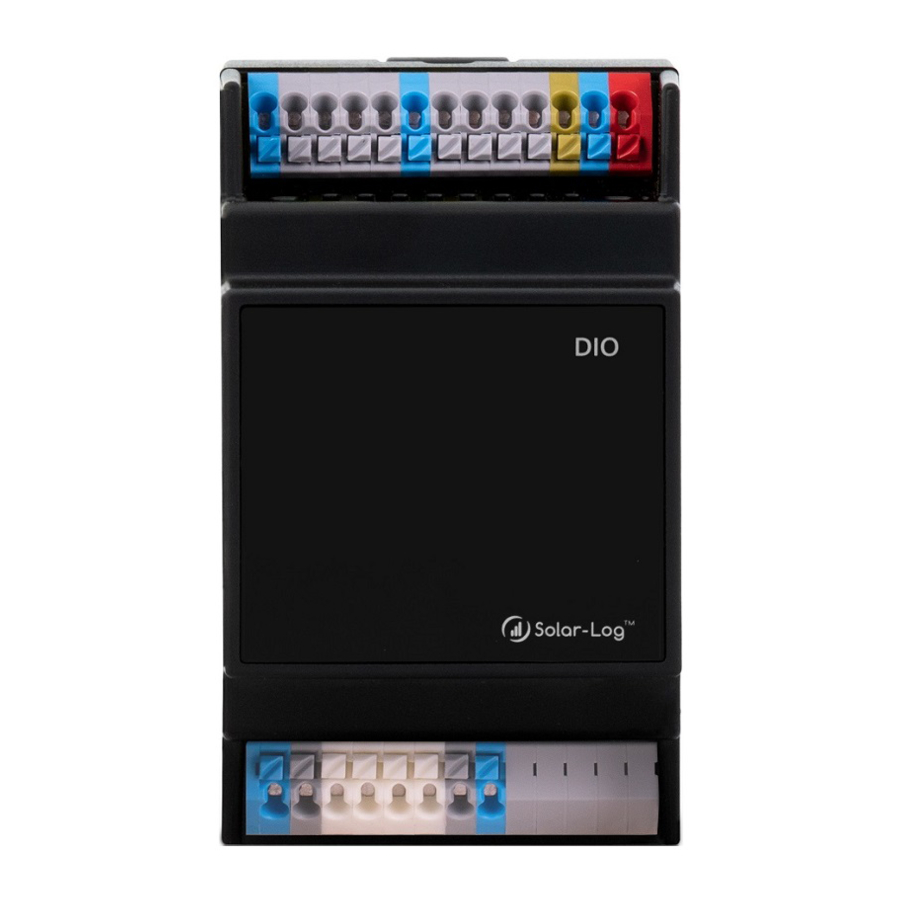
Module MOD I/O connection and mounting
Take one of the 2 bus connectors included in the scope of delivery. The bus con-
nector is plugged into the back of the Solar-Log Base.
Take the second bus connector and plug it into the back of the MOD I/O.
To complete the HBus connection, plug the two bus connectors together.
Now the connected housings can be snapped into the DIN rail.
Follow the short instructions Solar-Log Base.
Connections
Top
Currently without function
Power
-
+
Pin
MOD I/O
COM Functional earthing
1
Control signal active power
2
Digital_In 1
3
Digital_In 2
4
Digital_In 3
5
Digital_In 4
6
Control signal reactive power
COM Functional earthing
For further information on connecting the ripple control receiver, please refer
to the installation manual.
Technical Data
Device voltage
24V (+-5 %), in exceptional cases 12V (+-5 %)
With a power supply via the HBus: 250 mA
Total current of the outputs
With an external power supply: 1A
Solid conductor: 0.2 ... 1.5 mm² / 24 ... 16 AWG
Fine-stranded conductor: 0.2 ... 1.5 mm² / 24 ... 16 AWG
Cable cross-section
With ferrules: 0.14 ... 1 mm²/ 26 ... 18 AWG (ferrules
– to be used for fi ne-stranded conductor)
8.5 ... 9.5 mm / 0.33 ... 0.37 inch, with ferrules
Strip length
Please take into account the diameter of the plastic sleeves
Power consumption
min. 2 W
Voltage of the control signal corresponds to
Control signal
Supply voltage of the Solar-Log Base
Dimensions (Wx-
53,6x89,7x60,3
HxD) in mm
Solare Datensysteme GmbH • www.solar-log.com • Subject to change without notice • EN | 11.2020 | Version 1.4 | Art.Nr.: 15818
Bottom
PM+
Without function
6
5
4
3
2
1
≧
6mm / 0,24 inch
Advertisement
Table of Contents

Summary of Contents for Solar-Log MOD I/O
- Page 1 Now the connected housings can be snapped into the DIN rail. Dimensions (Wx- 53,6x89,7x60,3 HxD) in mm Follow the short instructions Solar-Log Base. Solare Datensysteme GmbH • www.solar-log.com • Subject to change without notice • EN | 11.2020 | Version 1.4 | Art.Nr.: 15818...
- Page 2 Spannung des Steuersignals entspricht Steuersignal Versorgungsspannung des Solar-Log Base Abmessung (BxHxT) in mm 53,6 x 89,7 x 60,3 Beachten Sie die Kurzanleitung Solar-Log Base. Solare Datensysteme GmbH • www.solar-log.com • Änderungen vorbehalten • DE | 11.2020 | Version 1.4| Art.Nr.: 15818...
Need help?
Do you have a question about the MOD I/O and is the answer not in the manual?
Questions and answers