Table of Contents
Advertisement
Quick Links
PM2.5-ROOM
Installation & Operation Instructions
GENERAL INFORMATION
"Particulate matter" (PM) is the general term used to
describe solid particles and liquid droplets found in
the air. The PM2.5 series of transmitters are designed
to detect particles less than 2.5 µm in diameter
include smoke, smog, bacteria, ne dust and liquid
droplets, and report the particle concentration of the
monitored environment. The unit utilizes a laser
particulate matter sensor to detect particle sizes
from 0.3 ~ 2.5 µm. The sensor has good long-term
stability with an accuracy 10% reading or 10 µg/m3.
The room unit features eld selectable outputs, 4-20
mA, 0-10 VDC, and Modbus RTU (RS485), relay, and
display.
The sensor has two jumper selectable working
modes for monitoring PM. The Normal Mode
monitors the environment continuously and Auto
Mode reduces the measuring time to extend service
life. The sensor default is set to Auto Mode.
IMPORTANT PRECAUTIONS
• This product uses a laser particulate matter
sensor. It is strictly prohibited to be
disassembled. It is dangerous if the human
body is exposed to the laser directly.
• If the environment exceeds the measurement
range for an extended period, it may lead to a
decrease of the measurement accuracy.
• The performance of the sensor may be
decreased due to excessive dust and oil mist,
etc. in extreme environments. (ie: high
humidity, high temperature)
• Avoid strong light into the housing.
• Avoid vibration.
MOUNTING INSTRUCTIONS
For optimal temperature readings, follow these
tips:
• Avoid air registers, di users, vents, and
windows
• Avoid con ned areas such as shelves, closed
cabinets, closets, and behind curtains.
Automation Components, Inc.
2305 Pleasant View Road | Middleton, WI 53562
Phone: 1-888-967-5224 | Website: workaci.com
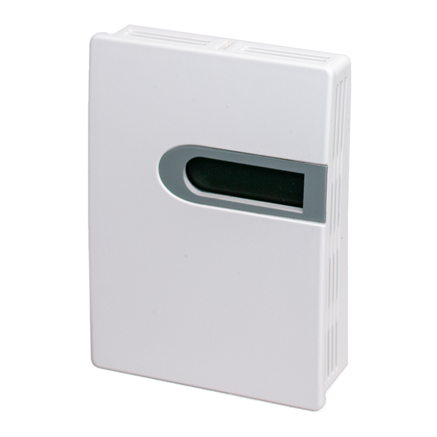
FIGURE 1: ENCLOSURE
DIMENSIONS
3.268"
(82.00 mm)
FIGURE 2: OPENING COVER
Separate the cover from the base by inserting a
at head screwdriver into the top slot marked
"OPEN". Pry the cover forward.
Attach the base directly to the wall or to a
standard 2" x 4" junction box using (2) #6-32 x 1"
screws.
• Eliminate and seal all wall and conduit
penetrations. Air migration from wall
cavities may alter readings.
• Do not install near heat sources. eg:
lamps,
radiators,
copiers, chimney walls, walls concealing
hot-water pipes
Page 1
Phone: 1-888-967-5224
Website: workaci.com
.984"
(25.00 mm)
1.205"
(30.60 mm)
direct
sunlight,
Version: 1.0
I0000941
Advertisement
Table of Contents

Summary of Contents for aci PM2.5-ROOM
- Page 1 PM2.5-ROOM Phone: 1-888-967-5224 Installation & Operation Instructions Website: workaci.com FIGURE 1: ENCLOSURE GENERAL INFORMATION DIMENSIONS “Particulate matter” (PM) is the general term used to .984" 3.268" describe solid particles and liquid droplets found in (25.00 mm) (82.00 mm) the air. The PM2.5 series of transmitters are designed to detect particles less than 2.5 µm in diameter...
- Page 2 DESTRUCTION OF ELECTRONIC CIRCUITS. Take care when mounting. Check local code for mounting height requirements. Typical mounting ACI recommends 16 to 26 AWG twisted pair wires heights are 48-60”(1.22-1.52m) o the ground and or shielded cable for all transmitters. at least 1.5’(0.5m) from the adjacent wall. The...
-
Page 3: Mode Selection
MODE SELECTION There are two working modes, automatic mode (AUTO) and continuous mode (NORMAL). AUTO mode will automatically reduce the measuring time to extend the service life of the sensor when the dust concentration changes very slightly. Use MODE jumper to choose the mode. The factory default mode is AUTO. -
Page 4: Modbus Rtu Interface
Relays parameters and descriptions: Mode Mode Description PARA. #1 PARA. #2 PARA. #3 PARA. #4 De nition Relay OFF Disable Relay Activate Relay Below Set Point Dead Actuate Restore Relay ON Dead band Relay OFF Set Point Band Delay(S) Delay(S) Set point Activate Relay Above Set Point... -
Page 5: Address Selection
The device that requests information is called the Modbus Master and the devices giving the information are Modbus Slaves. The Modbus sensors are slave devices and the number of Data Bits needs to be the same as in the Master device con guration. ACI’s Modbus RTU sensors utilize 8 data bits during communication exchange. -
Page 6: Modbus Rtu
SPECIAL MODE TO READ DATA FROM SLAVE With the special mode, customer can read the register data under the circumstance of NOT knowing the slave address. Address of special mode read data: 255(0xFF) Note: this operation is applicable for ONLY ONE slave in the network. MODBUS RTU Register Address Type... -
Page 7: Product Specifications
ABS Plastic / UL94V-0 WARRANTY The ACI PM Room Series are covered by ACI’s Two (2) Year Limited Warranty, which is located in the front of ACI’S SENSORS & TRANSMITTERS CATALOG or can be found on ACI’s web site: www.workaci.com. - Page 8 Automation Components, Inc. 2305 Pleasant View Road Middleton, WI 53562 Phone: 1-888-967-5224 Website: workaci.com Page 8 Automation Components, Inc. Version: 1.0 2305 Pleasant View Road | Middleton, WI 53562 I0000941 Phone: 1-888-967-5224 | Website: workaci.com...
Need help?
Do you have a question about the PM2.5-ROOM and is the answer not in the manual?
Questions and answers