Advertisement
Quick Links
Advertisement

Summary of Contents for Laing Innotech LTC Series
- Page 1 Installation and operating instruction LTC Series...
- Page 2 - 17 - Mounting: - 17 - Pairing of the control panel to the controller - 17 - Battery change - 18 - Mains connection - 18 - - 2 - Laing Innotech GmbH + Co. KG Althuette Germany Instruction LTC 11...
- Page 3 - 31 - Stroke limitation adjustment by “LD” control panels - 32 - Adjust stroke upper and lower limit - 32 - Delete stroke limits - 33 - Instruction LTC 11 Laing Innotech GmbH + Co. KG Althuette Germany - 3 -...
- Page 4 - 55 - Directives followed - 56 - Approval for European Controllers (230V versions) - 56 - Approval for USA and Canada (115V versions) - 56 - - 4 - Laing Innotech GmbH + Co. KG Althuette Germany Instruction LTC 11...
- Page 5 Whom is this document prepared for This document is an installation and operation instruction for the LTC series Laing Table Controllers and its accessories. The document is dedicated to manufacturers of height adjustable table frames and tables.
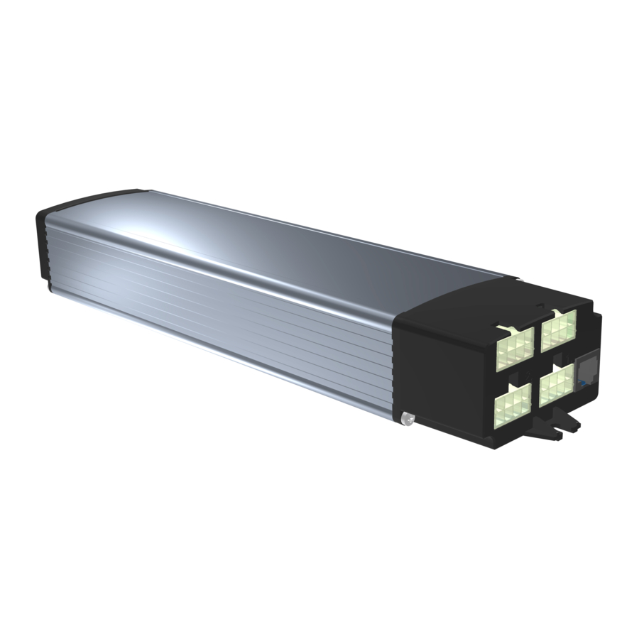
- Page 6 • Port for the OptoSense Sensor Laing Innotech GmbH + Co. KG Althuette Germany Instruction LTC 11 - 6 -...
-
Page 7: Specifications
-20°C to 60°C -4°F to 140°F Max. Environmental temperature for operation 5°C to 45°C 41°F to 113°F Max. Humidity for storage, transport and operation 95% non-condensing Instruction LTC 11 Laing Innotech GmbH + Co. KG Althuette Germany - 7 -... - Page 8 Dimensions Controller without OptoSense - 8 - Laing Innotech GmbH + Co. KG Althuette Germany Instruction LTC 11...
- Page 9 The power cable, the motor cables and control panels will be supplied in separate bulk package boxes. The OptoSense sensors too will be supplied in separate boxes. Fixing screws are not provided. Instruction LTC 11 Laing Innotech GmbH + Co. KG Althuette Germany - 9 -...
- Page 10 The controller with OptoSense can only be mounted directly below the table top. It cannot be mounted onto the cross bar! - 10 - Laing Innotech GmbH + Co. KG Althuette Germany Instruction LTC 11...
- Page 11 If the table can wobble the GyroSense may react to the wobbling instead of a collision. Instruction LTC 11 Laing Innotech GmbH + Co. KG Althuette Germany - 11 -...
- Page 12 - 12 - Laing Innotech GmbH + Co. KG Althuette Germany Instruction LTC 11...
- Page 13 Motor 1 • 2 Motor 2 • 3 Motor 3 (LTC 383 only) • 4 Motor 4 (LTC 384 only) • 5 Control panel and bus connection Instruction LTC 11 Laing Innotech GmbH + Co. KG Althuette Germany - 13 -...
- Page 14 RS 485 A Ground RS 485 B Hall sensor +5 V External +5V power Optional 2 Analog control panel Optional 1 Ground Hall sensor 2 Motor connection 2 - 14 - Laing Innotech GmbH + Co. KG Althuette Germany Instruction LTC 11...
- Page 15 The connections must be made as shown on the picture. One connection is made to the controller, one to a control panel with height indication, one to a control panel without height indication. Instruction LTC 11 Laing Innotech GmbH + Co. KG Althuette Germany - 15 -...
- Page 16 When the OptoSense is used there is no control panel required! The OptoSense is ready to use after insertion into the controller. In addition to the OptoSense another control panel can be connected. - 16 - Laing Innotech GmbH + Co. KG Althuette Germany Instruction LTC 11...
- Page 17 To connect another keyboard or to connect the keyboard to another controller, perform the described pairing procedure again with a different keyboard or a different controller. Instruction LTC 11 Laing Innotech GmbH + Co. KG Althuette Germany - 17 -...
- Page 18 Make sure the power cable will be placed in a way what provides stain relief to the plug so that the plug cannot be pulled out of the controller. Laing Innotech GmbH + Co. KG Althuette Germany Instruction LTC 11 - 18 -...
- Page 19 Please note that the sensitivity of the current based collision detection on down ward movements is reduced drastically if the table is loaded with some weight! Instruction LTC 11 Laing Innotech GmbH + Co. KG Althuette Germany - 19 -...
- Page 20 • Reaching a limit switch at the lower end what disconnects the motor The method how to acquire the reference position must be set in the Wizard. Laing Innotech GmbH + Co. KG Althuette Germany Instruction LTC 11 - 20 -...
- Page 21 The connection is made through the safety adapter what provides an RJ45 connector where the safety devices can be connected. Instruction LTC 11 Laing Innotech GmbH + Co. KG Althuette Germany - 21 -...
- Page 22 Drawn By: File: D:\Drive the customer is shown in bolt in bolt lines. lines. The 100 Ohm resistor represents the contact resistance of the ribbon switch. Laing Innotech GmbH + Co. KG Althuette Germany Instruction LTC 11 - 22 -...
- Page 23 Whether memory positions are stored in a new controller depends on the parameter set entered into the controller when configured by the table supplier. Instruction LTC 11 Laing Innotech GmbH + Co. KG Althuette Germany - 23 -...
- Page 24 • From now on height stored in the memory position can be adjusted by pressing and holding pressed the selected memory key until the table stops at the height stored - 24 - Laing Innotech GmbH + Co. KG Althuette Germany Instruction LTC 11...
- Page 25 If the table top is at the lower position and the adjustment for the lower position shall be deleted press the “down” arrow key. • Successful deletion of the position will be confirmed by a sound Instruction LTC 11 Laing Innotech GmbH + Co. KG Althuette Germany - 25 -...
- Page 26 Before the stroke limits are adjusted, the user height limits have to be deleted when the stroke limits will reach into the user height limit range! - 26 - Laing Innotech GmbH + Co. KG Althuette Germany Instruction LTC 11...
- Page 27 If the table top is at the lower position and the adjustment for the lower position shall be deleted press the “down” arrow key. • Successful deletion of the position will be confirmed by a sound Instruction LTC 11 Laing Innotech GmbH + Co. KG Althuette Germany - 27 -...
- Page 28 If not, you must select the selection “1” where the movement can be stopped by releasing the key - 28 - Laing Innotech GmbH + Co. KG Althuette Germany Instruction LTC 11...
- Page 29 P06 for deletion of the lower height limit select, the table must be at the lowest position o P07 for deletion of the upper height limit select, the table must be at the highest position Instruction LTC 11 Laing Innotech GmbH + Co. KG Althuette Germany - 29 -...
- Page 30 To change the indication, proceed as follows: • Press the “up” arrow key 4 times quickly one after another • Reaching the program mode will be confirmed by a sound - 30 - Laing Innotech GmbH + Co. KG Althuette Germany Instruction LTC 11...
- Page 31 Memory position 1 to 4 Upper user limit Lower user limit Button mode Collision detection Unit used in the display Precision of the indication in the display Instruction LTC 11 Laing Innotech GmbH + Co. KG Althuette Germany - 31 -...
- Page 32 The top and lower positions must keep a minimum distance so that the table can still move after the new limits have been adjusted. This minimum distance is defined in the parameter set entered into the - 32 - Laing Innotech GmbH + Co. KG Althuette Germany Instruction LTC 11...
- Page 33 • Press the “memory one” key shortly to enter the setting mode. • Press the “up” or “down” arrow key to shift the indicated height until the desired heigth is shown on the display Instruction LTC 11 Laing Innotech GmbH + Co. KG Althuette Germany - 33 -...
- Page 34 “1” BLE activated • Press the “memory one” key shortly to confirm the selection • To leave the menu item press the “memory two” key - 34 - Laing Innotech GmbH + Co. KG Althuette Germany Instruction LTC 11...
- Page 35 • Press the “memory one” key shortly to enter the pairing mode • The controller will now be for 15 seconds in pairing mode, throughout this time the controller can be paired with a wireless control panel Instruction LTC 11 Laing Innotech GmbH + Co. KG Althuette Germany - 35 -...
- Page 36 When the number of motors is reduced, due to safety reasons the controller will not start the motors as someone might have forgotten to plug in a motor. - 36 - Laing Innotech GmbH + Co. KG Althuette Germany Instruction LTC 11...
- Page 37 • Press the “memory one” key shortly to confirm the selection • To leave the menu item press the “memory two” key Instruction LTC 11 Laing Innotech GmbH + Co. KG Althuette Germany - 37 -...
- Page 38 • If, after activation, the hand is not moved for about 2 seconds, the sensor will deactivate until the hand or any other object is removed. - 38 - Laing Innotech GmbH + Co. KG Althuette Germany Instruction LTC 11...
- Page 39 Every connected control panel, including the OptoSense, WiFi and BLE in the connected controllers can be assigned to one or more groups. Instruction LTC 11 Laing Innotech GmbH + Co. KG Althuette Germany - 39 -...
- Page 40 So, in this mode only the HUB has to be configured, the controllers then will be configured by the HUB automatically. - 40 - Laing Innotech GmbH + Co. KG Althuette Germany Instruction LTC 11...
- Page 41 Through the App or the Wizard, the controller can be given a name, what then will be shown instead of the serial number. The BLE module can provide all informations available inside the controller e.g. to an App. Instruction LTC 11 Laing Innotech GmbH + Co. KG Althuette Germany - 41 -...
- Page 42 In case of a problem or a configuration requirement the Cloud Interface will be sent to the customer, the customer will connect it with a few simple steps, then Laing Innotech GmbH + Co. KG Althuette Germany Instruction LTC 11 - 42 -...
- Page 43 Instruction LTC 11 Laing Innotech GmbH + Co. KG Althuette Germany - 43 -...
- Page 44 Failure mode 1 out the combination of long and short signals and refer to the failure modes described below - 44 - Laing Innotech GmbH + Co. KG Althuette Germany Instruction LTC 11...
- Page 45 Change from metric to Here the indicated units imperial units can be changed from five sounds metric to imperial and back Instruction LTC 11 Laing Innotech GmbH + Co. KG Althuette Germany - 45 -...
- Page 46 Set user upper limit Users can set individual upper limits for their - 46 - Laing Innotech GmbH + Co. KG Althuette Germany Instruction LTC 11...
- Page 47 This menu item leads to Enter Reset menu the Reset menu Service Menu Reset user settings All user settings will be reset to the factory settings Instruction LTC 11 Laing Innotech GmbH + Co. KG Althuette Germany - 47 -...
- Page 48 Clear paired control All connections to panels control panels saved in the controller will be deleted The private mode for the Reset private mode controller will be deactivated - 48 - Laing Innotech GmbH + Co. KG Althuette Germany Instruction LTC 11...
- Page 49 Shows the actual battery temperature Reset Menu Adjust/reset the number Motor number of motors set in the controller Reset safety mode to Safety mode auto detect mode Instruction LTC 11 Laing Innotech GmbH + Co. KG Althuette Germany - 49 -...
- Page 50 If the Error remains short long short short restart system by unplugging the power cable of the controller and plugging it in again after 20 seconds. - 50 - Laing Innotech GmbH + Co. KG Althuette Germany Instruction LTC 11...
- Page 51 Motor current reached Reduce load on the the overcurrent stop table. LED blinking: level Instruction LTC 11 Laing Innotech GmbH + Co. KG Althuette Germany - 51 -...
- Page 52 13 minutes are required Reset error by pressing any key. - 52 - Laing Innotech GmbH + Co. KG Althuette Germany Instruction LTC 11...
- Page 53 LED blinking: speed up smoother travel path of the table mechanism long long long long Reset error by pressing any key. Instruction LTC 11 Laing Innotech GmbH + Co. KG Althuette Germany - 53 -...
- Page 54 20 seconds. If the error reoccurs the controller may be damaged, contact the supplier - 54 - Laing Innotech GmbH + Co. KG Althuette Germany Instruction LTC 11...
- Page 55 OptoSense activated The sound indicates that the OptoSense sensor has been activated The sound confirms a OK Signal selection Instruction LTC 11 Laing Innotech GmbH + Co. KG Althuette Germany - 55 -...
- Page 56 ISO 13849-2 Performance level „B“ Approval for USA and Canada (115V versions) ETL Mark Approval is based on the following standards: ANSI/UL 60950-1:2007+A1+A2 CAN/CSA-22.2 No. 60950-1:2007+ A1+A2 Revision_11_E, 27.6.2019 - 56 - Laing Innotech GmbH + Co. KG Althuette Germany Instruction LTC 11...
- Page 57 Instruction LTC 11 Laing Innotech GmbH + Co. KG Althuette Germany - 57 -...
Need help?
Do you have a question about the LTC Series and is the answer not in the manual?
Questions and answers