Table of Contents
Advertisement
Available languages
Available languages
Quick Links
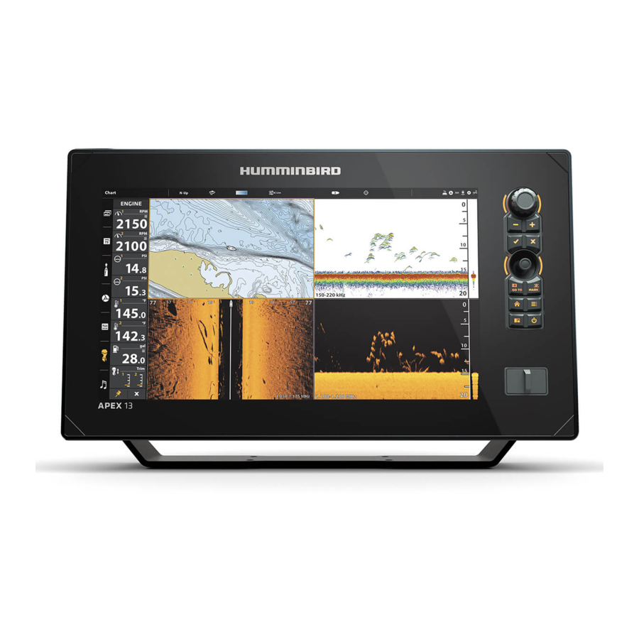
APEX™ SERIES CONTROL HEAD Installation Guide
Follow the instructions in this installation guide to gimbal mount the control head.
Read the instructions in this transducer guide completely to understand the mounting guidelines
before starting the installation.
Visit our Web site at humminbird.com for additional information and resources for transducer
installations. Also, visit youtube.com/humminbirdtv for informational videos.
Supplies: In addition to the hardware supplied with your control head, you will need a powered
hand drill and various drill bits, flat head screwdriver, pencil, safety glasses and dust mask, marine-
grade silicone sealant, dielectric grease (optional), extension cables (optional), Ethernet cables
(optional), and accessory cables (optional). Also, see Connect Power to determine the type of
connection, fuse size, and additional equipment you will need for the installation.
Accessories and Ethernet: Accessories and Ethernet equipment are available for purchase at
humminbird.com. The installation guides are available with the product, or they can be downloaded
from our Web site.
Installation Overview
1
| Plan the Mounting Location
Pre-assemble the control head to plan the best mounting location.
1. Place 1 metal washer onto each gimbal knob.
2. Place 1 rubber washer onto each gimbal knob.
3. Install the gimbal knobs (with washers) into each side of the control head. Tighten the knobs
just enough so you can slide the control head into the gimbal bracket arms.
4. Install the control head into the arms of the bracket mount. Confirm the opening in the gimbal
bracket arms faces the rear of the control head. Confirm the ratchets on the bracket and
control head fit together.
rubber
washer
metal
washer
gimbal
knob
bracket arm opening
If you prefer to mount the control head overhead, flip the bracket to the top of the control
head. The opening in the gimbal bracket arms must face the rear of the control head.
NOTE: Overhead and/or thin panels may require additional hardware (separate purchase
required) to securely mount the control head.
5. Hand-tighten the gimbal knobs to secure the control head to the gimbal bracket.
Installation Preparation
Assembling the Control Head and Bracket
1
532744-1_A
Overhead Mount
back of bracket
Advertisement
Table of Contents

Summary of Contents for Hummingbird APEX 13
- Page 1 APEX™ SERIES CONTROL HEAD Installation Guide 532744-1_A Follow the instructions in this installation guide to gimbal mount the control head. Installation Preparation Read the instructions in this transducer guide completely to understand the mounting guidelines before starting the installation. Visit our Web site at humminbird.com for additional information and resources for transducer installations.
- Page 2 3. Place one flat washer onto each #10 x 1" wood screw. Insert the four screws with washers into the mounting holes and tighten them until they are secure (see the illustration Installing the Gimbal Bracket). Hand tighten only! Installing the Gimbal Bracket Bracket Hole Pattern Measurements (APEX 16 and APEX 13) bracket arm 1.50" 1.50 opening 4.50"...
-
Page 3: Connect Power
Δ Power Supply: The control head must be connected to a 12 VDC power supply using the fuse size shown in the Required Fuse Size table. Required Fuse Size Model Fuse Size Fuse Type APEX 13 slow-blow or MDL equivalent APEX 16 7.5A slow-blow or MDL equivalent APEX 19 7.5A... - Page 4 APEX™ SERIES CONTROL HEAD Installation Guide 532744-1_A 1. Confirm that the power cable is disconnected from the control head. 2. Connect the power cable wires to the fuse panel or battery as follows: Fuse Terminal Connection: Use crimp-on type electrical connectors (not included) that match the terminal on the fuse panel.
- Page 5 APEX™ SERIES CONTROL HEAD Installation Guide 532744-1_A 6. Connect each cable to the appropriate ports on the control head. The ports are labeled, and the connectors are keyed to prevent incorrect installation. APEX Connector Panel 7. Hand-tighten the screw nut on each cable to secure the connection. See the illustration Routing the Cables Behind the Bracket.
- Page 6 APEX™ SERIES CONTROL HEAD Installation Guide 532744-1_A 5. Select Settings > Network > System Info. GPS: Confirm the GPS is listed as Enhanced Fix or 3D Fix. Confirm that a latitude/longitude position is displayed in the Position digital readouts section. Accessories: Review the list to confirm accessories are listed as connected.
-
Page 7: Contact Humminbird
APEX™ SERIES CONTROL HEAD Installation Guide 532744-1_A Contact Humminbird Web site: humminbird.com ENVIRONMENTAL COMPLIANCE STATEMENT: It is the intention of Johnson Outdoors Marine Electronics, Inc. to be a responsible corporate citizen, E-mail: service@humminbird.com operating in compliance with known and applicable environmental Telephone: 1-800-633-1468 regulations, and a good neighbor in the communities where we make or... -
Page 8: Préparation De L'installation
TÊTE DE COMMANDE DE LA SÉRIE APEX Guide d'Installation 532744-1_A Suivez les directives de ce guide pour monter la tête de commande sur un support à cardan. Préparation de l'installation Lisez complètement les instructions de ce guide pour comprendre les directives avant de commencer l'installation. - Page 9 Trou Support Motif Mesures avec les rondelles sur les trous de montage et les serrer jusqu'à ce qu'ils soient sécurisés (voir (APEX 16 and APEX 13) l'illustration Installation du support à cardan). Serrez les vis à la main seulement! 1.50"...
-
Page 10: Brancher L'alimentation
12 V c.c. à l'aide de la taille du fusible indiqué dans le tableau des Tailles Requis Fusible. Tailles Requis Fusible Modèle Taille du Fusible Type de Fusible APEX 13 fusible temporisé ou équivalent fusible MDL APEX 16 7.5A fusible temporisé ou équivalent fusible MDL APEX 19 7.5A... - Page 11 TÊTE DE COMMANDE DE LA SÉRIE APEX Guide d'Installation 532744-1_A AVERTISSEMENT ! Certains bateaux sont munis de systèmes électriques de 24 V ou 36 V, mais la tête de commande DOIT être branchée à un bloc d’alimentation de 12 V c.c. AVERTISSEMENT ! Assurez-vous que le câble d’alimentation n’est pas branché...
- Page 12 TÊTE DE COMMANDE DE LA SÉRIE APEX Guide d'Installation 532744-1_A Acheminement des câbles derrière le support 6. Puis branchez-les sur les connecteurs appropriés de la tête de commande. Les ports sont étiquetés et les connecteurs de câbles sont également marqués afin d'éviter toute erreur d'installation.
- Page 13 TÊTE DE COMMANDE DE LA SÉRIE APEX Guide d'Installation 532744-1_A toucher pour sélectionner ouvir sélectionner 3. Sélectionnez le mode Pêcheur. Suivez les invites à l'écran pour configurer l'appareil. Le mode Pêcheur est le moyen le plus rapide de configurer la tête de contrôle avec moins de paramètres de menu pour obtenir de la manière.
- Page 14 TÊTE DE COMMANDE DE LA SÉRIE APEX Guide d'Installation 532744-1_A Pour communiquer avec Humminbird DÉCLARATION DE CONFORMITÉ AVEC L’ENVIRONNEMENT : Johnson site Web : humminbird.com Outdoors Marine Electronics, Inc. entend agir en de façon responsable, et 532744-1_A Courrier électronique : service@humminbird.com respecter la réglementation environnementales connues et applicables et la politique de bon voisinage des communautés où...
Need help?
Do you have a question about the APEX 13 and is the answer not in the manual?
Questions and answers