
Related Manuals for ECOSTAR ECO 1.0


Summary of Contents for ECOSTAR ECO 1.0
- Page 1 SQUARE BODY MONOBLOCK LIGHT OIL BURNERS INSTALLATION, OPERATING AND MAINTENANCE MANUAL ONE STAGE AND TWO-STAGE OPERATION ECO 1.0 ECO 2.0 ECO 30.0 www.ecostar.com.tr 19.10.2018 Rev. 07...
- Page 2 DEAR USER, ECOSTAR ECO 1.0, ECO 2.0, ECO 30.0 Square Body Light Oil burners are prepared and manufactured according to the latest technical developments and safety rules. It is easy to use for our customers. We recommend that you read this manual and safety warnings thoroughly before the use of the device in order to ensure safe, cost effective and environmental-friendly use.
-
Page 3: Table Of Contents
CONTENTS WARNINGS ............................3 1.1. Warning Symbols and Descriptions ..................... 3 1.2. General Safety Rules ........................4 TERMS OF WARRANTY ........................6 2.1. Out of Warranty Conditions ......................6 BURNER’S GENERAL FEATURES ....................7 3.1. Purpose of Use and Work Limits of Burners ................7 3.2. -
Page 4: Warnings
1. WARNINGS 1.1. Warning Symbols and Descriptions Symbols Symbol Descriptions Important information and useful hints. Warning of danger to life or property. Warning of electrical voltage. Product handling information. Flame tube adjustment 1st and 2nd Stage selection switch Carry in an upright position. Fragile Item. Protect against water. 19.10.2018 Rev. -
Page 5: General Safety Rules
1.2. General Safety Rules • All personnel engaged in installation, disassembly, commissioning, operation, control, maintenance and repair should have received the necessary training and fully read and understood this manual. • No changes that might damage the safety of the burner unit must be made by persons and/or organizations on the burner unit. - Page 6 Check combustion values to be correct by using flue gas analysis at the whole adjustment range between minimum, full load, and ignition load. Use lifting device or belt for lifting fan motor, if necessary. During the first commissioning of the burner or in case of any revision carried out in the electrical system or motor cables by any reason, direction of the fan rotation must certainly be checked by the authorized technical service.
-
Page 7: Terms Of Warranty
2. TERMS OF WARRANTY Main and auxiliary equipment and all components used in Ecostar light oil burners are guaranteed for 1 year by TERMO ISI SIST. A.Ş starting from the date of commissioning under the maintenance, adjustment, operating conditions and relevant mechanic, chemical and thermal effects explained herein. -
Page 8: Burner's General Features
3. BURNER’S GENERAL FEATURES ECOSTAR light oil burners are designed to operate with oil at 2.5 – 6 Cst (mm²/s) viscosity, at rated capacity and pressure ranges and -15% to +10% nominal voltage. 3.1. Purpose of Use and Work Limits of Burners •... - Page 9 Temperature change of fuel used in ECOSTAR light oil burners dependent on viscosity 19.10.2018 Rev. 07...
-
Page 10: Burner Components
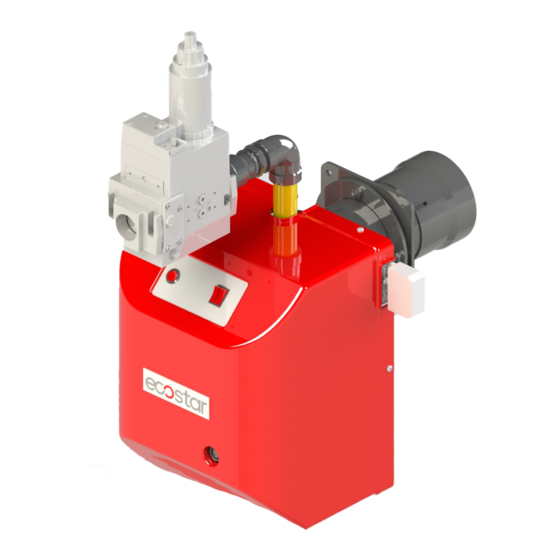
3.3. Burner Components ECO 1.0 Assembly No Part Name Assembly No Part Name Housing cover Air klappe Relay Air klappe adjusting screw Fuel pump Cover Pump-lance connecting Body group Ignition transformer Filter Motor Lance Installation sheet Flame tube Boiler connection flange... - Page 11 ECO 2.0-ECO 30.0 Assembly No Part Name Assembly No Part Name Housing cover Relay Air klappe Fuel pump Air klappe drive shaft Ignition transformer Electric installation sheet Servomotor Spiral casing Motor Electric connection socket Bulls eye Flame tube Service cover Boiler connection flange Lance Flame tube extension...
-
Page 12: Technical Data
Kcal/h Kcal/h Kg/h ONE STAGE LIGHT OIL BURNERS ECO 1.0 OL C 1 10.200 35.700 0,15 1N 230 ECO 1.0 OL C 1 a 15.300 51.000 0,15 1N 230 ECO 1.0 OL C 1 b 20.400 71.400 0,15 1N 230 ECO 1.0 OL C 1 c... -
Page 13: Back Pressure-Capacity Diagrams
4.2. Back Pressure-Capacity Diagrams 19.10.2018 Rev. 07... - Page 14 19.10.2018 Rev. 07...
- Page 15 19.10.2018 Rev. 07...
-
Page 16: Burner Dimensions
4.3. Burner Dimensions 4.4. Flame Length and Diameter 4.5. Noise Level Product operates within the range of 70 decibels max. and 74 decibels. 19.10.2018 Rev. 07... -
Page 17: Burner Handling Information
• Do not leave the product in wet environment. Dimensions of the box used for handling Burner L x W x H (cm) Weight (kg) ECO 1.0 70 X 33 X 35 65 X 36 X 47 ECO 2.0 75 X 43 X 54 ECO 30.0... -
Page 18: Installation
6. INSTALLATION 6.1. Burner Installation Picture 1- Drift Bolts 2- Burner Body 3- Boiler Connection Flange 4- Gasket 5- Boiler Studs Ø In the installation of the burner, use the installation materials supplied with the burner. Ø Secure the burner connection flange onto the burner cover by 4 bolts. Gasket must be connected such that it will remain between connecting flange and boiler cap. -
Page 19: In Reverse Flame Front Mirror Boilers
6.2. In reverse flame front mirror boilers While installing the burner in reverse flame front mirror boilers, flame tube tip must be adjusted such that it gets inside by 50 mm-100 mm from flue pipes (50mm≤A≤100mm). Otherwise flue gas temperature will rise and fuel consumption will increase. -
Page 20: Commissioning
7. COMMISSIONING 7.1. Before Commissioning Electrical connection Perform electrical connections according to the diagram provided with the burner. Follow general security rules during installation of electric wiring and making connections. Connect the earthing terminal in electric panel to the earthing installation. 7.2. -
Page 21: Combustion Adjustment
7.3. Combustion Adjustment Ø Fuel nozzle Use proper wrench in installation and dismantle of the fuel nozzle. Use diesel oil to clean the fuel nozzle. Do not use thinner and its derivatives. Ø Photocell Check the photocell weekly. Clean the dust or fume stains on the glass of photocell by a dry cloth. - Page 22 Ø One Stage Light Oil Burner Fuel Circuit Ø Two Stages Light Oil Burner Fuel Circuit 19.10.2018 Rev. 07...
-
Page 23: Servomotor Adjustment
7.5. Servomotor Adjustment Ø SQN70 At Two-stage Burners; I. Red Cam: Adjusts 2nd level max. air. II. Blue Cam: Resets the clamp. III. Orange Cam: Adjusts 1st level min. air. IV. Black Cam: Adjusts 2nd level valve opening degree. Do not open servomotor. Do not interfere with. It may damage servomotor or change burner settings. -
Page 24: Program Relay
7.7. Program Relay LOA 24 Ø Red led on: Indicates burner malfunction. Ø If the burner switches to the fault mode, please wait at least 30 seconds and reset the program relay. Press and hold the light button for 2 sec. to reset the program relay. 19.10.2018 Rev. -
Page 25: Light Oil Burner Fuel Ring Line
7.8. Light Oil Burner Fuel Ring Line 19.10.2018 Rev. 07... -
Page 26: Maintenance
8. MAINTENANCE 8.1. Weekly Maintenance Weekly maintenance is a routine cleaning and adjustment procedure which is performed to ensure smooth and continuous operation of the system. Burner components must be adjusted after each maintenance work in accordance with the instructions. Otherwise, the burner cannot be operated efficiently. -
Page 27: Seasonal Maintenance
8.3. Seasonal Maintenance Comprehensive maintenance work when the burner is re-started after long periods of shut-down or interruptions. After completion of maintenance and adjustment processes, make sure to perform a combustion analysis. Ø Check insulation resistance of electric motor. Ø Make surface cleaning of ignition electrodes and porcelains. Replace cracked or broken porcelains. -
Page 28: Installation And Disassembly Instructions For Maintenance Purposes
8.4. Installation and Disassembly Instructions for Maintenance Purposes 1. Remove 2 bolts on burner top cover and detach the top cover from the body. 2. Remove bolts number 2 on the 2nd electric installation sheet. 3. Remove bolts number 3 on service cover and detach the installation sheet from the spiral casing. - Page 29 6. Remove bolts number 6 on the installation sheet. 7. Detach the installation sheet from the spiral casing. 8. Perform maintenance of the fan group. Perform the installation by following the reverse of the method you have followed during disassembly. Be careful to connect the components correctly during installation after maintenance 19.10.2018 Rev.
-
Page 30: Troubleshooting
9. TROUBLESHOOTING Problem Cause Explanation-Suggestion Fuel is cut or does not Fuel valve might be closed. Open the valve. come Check burner power supply. The fuse on the Fuse failure main panel or the fuse on the burner might be tripped. -
Page 31: Periodical Flue Gas Measurement Report
10. PERIODICAL FLUE GAS MEASUREMENT REPORT Fuel Yield Flue Consumption (ppm) (ppm) (ppm) Temp. Date Signature (kg/h) (ºC) 19.10.2018 Rev. 07... -
Page 32: After Sales Services
Fax: +90 282 685 42 09 Also you can contact with us: Web site : www.ecostar.com.tr E - mail : servis@ecostar.com.tr Please observe the following recommendations. • Use the product in accordance with the principles of this manual. • For any service demands regarding the product, please contact our Service Center from the abovementioned phone numbers. -
Page 33: Notes
12. NOTES Please record and forward your measurements and observations to us www.ecostar.com.tr 19.10.2018 Rev. 07...
Need help?
Do you have a question about the ECO 1.0 and is the answer not in the manual?
Questions and answers