Table of Contents
Advertisement
Quick Links
USER MANUAL
BIOSLIM
SMART-I ELECTRONICS SYSTEMS PVT. LTD.
An ISO 9001:2008 certified company
Units No 250 to 252, Second Floor, Building No D-7, Bhumi World, Pimplas Village, Bhiwandi,
Thane-421302, Maharashtra. INDIA. Contact:- (+91) 7039047042 , (+91) 02522-661518
Web: www
ystems.com E-mail: enquir
ystems.com
PRESENCE: MUMBAI-DELHI-BANGALORE–KOLKATA-CHENNAI-AHMEDABAD–PUNE-HYDERABAD
Advertisement
Table of Contents

Summary of Contents for Smart I BIOSLIM
- Page 1 USER MANUAL BIOSLIM SMART-I ELECTRONICS SYSTEMS PVT. LTD. An ISO 9001:2008 certified company Units No 250 to 252, Second Floor, Building No D-7, Bhumi World, Pimplas Village, Bhiwandi, Thane-421302, Maharashtra. INDIA. Contact:- (+91) 7039047042 , (+91) 02522-661518 Web: www ystems.com E-mail: enquir ystems.com...
- Page 2 Please familiarize yourself with these instruc ons, before a emp ng to install the BIOSLIM. Because prolonged reliable and trouble-free opera on will only be ensured if it is fi ed properly. We hope your new BIOSLIM will bring you las ng safety and effec ve opera ons for your employee a endance.
-
Page 3: Table Of Contents
Descrip on of keys & other parts____________________________________________ 7 Keypad Menu Details______________________________________________________7 How to Use______________________________________________________________8 Moun ng Plate Details____________________________________________________21 Bioslim Connec on details_________________________________________________23 Bioslim Connnector wire details _____________________________________________24 Bioslim Reader connec on details___________________________________________25 Standalone Bioslim Configura on___________________________________________ 26 Connec ng To Host Computer______________________________________________27 Enrollment Process_______________________________________________________30 Trouble Shoo ng_________________________________________________________32 The Contained in This Manual are Subject To Change without No ce at Any Time. -
Page 4: Warning & Cau On
Warning & Cau on Please handle the equipment with care. Physical Damage to the system is not covered under warranty. Do not power on the system without reading this manual. Ensure proper power supply with Earthing. Note down the serial number and model no. of the device for future reference and quote in all support and service requests. - Page 5 Upload/Download Op on in So ware (Refer User Manual of So ware for taking finger prints backup and uploading the backup finger prints back to the Bioslim devices.) Care should be taken iden fying the wires. Improper wiring may render permanent damage to the device or personal injury.
-
Page 6: Get Started With Bioslim
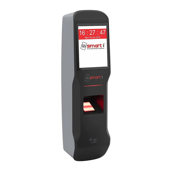
Get started with Bioslim Included items: Product Image Bioslim A endance System Supplying power for Power Supply the Biometric Unit For Device Configura on/ h p://www.smar systems. So ware CD Management & For com/So ware.html Data Downloading For referring func ons... -
Page 7: Specifica On
Specifica on Hardware Specifica on: Descrip on Par culars 32 Bit RISC Arm Memory Upto Flash 8 MB Events/Transac ons 1,00,000 No. of templates in sensor 1900/19000 No. of Users 7500 Opera on Modes UID/Card + Finger UID/Card only Card + Finger Card Only UID/CARD+F+ PIN UID /card +pin Card only + pin UID only + pin Finger only Card &... -
Page 8: Descrip On Of Keys & Other Parts
Introduc on The new BIOSLIM blends loads of innova ve features to streamline installa on and administra on for small, medium or, large business enterprises for standalone door access control deployment. BIOSLIM brings the high speed, accuracy, flexibility and user friendly interac vity. -
Page 9: How To Use
How to Use: Step 1.: Enrollment Process 1. Do Admin login 15 : 39 : 15 Tue 19 Feb 2019 Press on menu key Enter admin id >> 11111(Default admin id) > press Enter . Enter password >>12345(Default password) > press Enter . 2. - Page 10 Step 1.: Enrollment Process 1. Press on Network icon 2. Select Network Se ng > Enter 3. In this menu user can edit the various parameters such as, unit IP address, subnet mask, default gateway, server IP address …..etc. User have to set various parameters such as, *IP Address *Subnet mask *Gateway...
- Page 11 HOME SCREEN 15 : 39 : 15 Home A er Power ON , these screen will be displayed as per Screen mode selected (a)If System>>Sensor>>Iden fy mode>> Enable> Thumb print symbol will be Displayed (b)By default only Home key is displayed in normal condi on (c)If System>>Allow UID by Key >>...
- Page 12 ADMIN ADMIN Admin 1: Set Time 1. Set Time Select op on 1)Will allow to set Time as require 2: Set Date press enter key i. hh:mm:ss 3: Add Admin ID ii. hh:mm 4: Delete Admin ID 2)Try to set invalid TIME> 5: Change Password It will not allow to set 2.
- Page 13 USER USER User 1: Ad User 1. Add User 1)Enter User ID & 1) User to get added properly with proper presenter. It will ask Pin number and finger. 2: Del User for finger 2) ON memory full it should show 3: Search User 2)If finger is already "memory full"...
- Page 14 SYSTEM SYSTEM System 1: Set Slave ID 1. Set Slave 1) Enter Slave No Proper Slave ID should be set with 2: Set Controller No from 1 to 128. "slave ID Updated" message 3: Sensor 4: Controller Type 2: Set 1) Controller Proper controller number should 5: Weigand Out Reader...
- Page 15 5. Weigand 1) Select any one This applicable only in weigand out. Bits op on out of The bit will send to controller 7op on according bit set. 1=Weigand 26 2=Weigand 32 3=Weigand 34 4=Weigand 26 or card 5=Weigand 32 orcard6=Weigand 26 or transparent...
- Page 16 NETWORK NETWORK Network 1. Network 1) Select All network should get set properly 1: Network Se ng accordingly to check a er off/on unit. Se ng 2: MAC Secu. EN/DS make changes Refer Annexure B 3: TCPPush EN/DS i. Ip address 4: TCPPush Porto.No.
- Page 17 TROUBLE SHOOT TROUBLESHOOT Trouble shoot 1. Ini alize 00 Delete all data Should have show all message 1: Ini alise System 01 Delete System properly on display. 2: Wiegand Display Transac on 3: Network Test 02Delete All Users 03Set All Default 04Delete Sys.
- Page 18 DEVICE INFO DEVICE INFO Device info Display All Shows All parameter related to 1: Ini alise System Parameter system. 2: Wiegand Display 3: Network Test Disp Useful Model Number It shows Reader No, Weigand Bits of Parameter Unit ID Controller par cular card No Card Buffer Used Card Buffer...
- Page 19 Annexure A Security level se ng Security level specifies FAR (False Acceptance Ra o). If it is set to “Level 2” i.e. 1/100,000, it means that the probability of accep ng false fingerprints is 1/100,000. The following table shows the rela onships between the automa c security levels and the number of enrolled templates.
- Page 20 Annexure B Network se ng Network Se ng Sr. No. Descrip on Parameters Set IP address to device for TCP/IP communica on IP Addres As per your network. Subnet Mask As per your network. Gateway For device iden fica on and communica on Local TCP Port For device iden fica on and communica on Local UDP Port...
- Page 21 Annexure C Procedure for configuring users for Dual Authen ca on 1) Firstly You have to Login à Press Home key à Enter Admin ID “ 11111” à Press Enter à Password “12345” à Press Enter. 2) Enroll the finger for Users from User menu. Go in User menuàEnter in Add user à...
-
Page 22: Moun Ng Plate Details
Moun ng Plate Details Pan head self threaded star (M3*10) screw in wall 30.0 mm 11.0 mm 11.0 mm 18.0 mm Pan head self threaded star (M3*10) screw in wall 30.0 mm 40.0 mm Pan head self threaded star (M3*10) screw in wall... - Page 23 Notch to Fit the Device Notch to Fit the Device...
-
Page 25: Bioslim Connnector Wire Details
Bioslim Connector WIRE details PIN DESCRIPTION WIRE Power POWER + (12Vdc) POWER - BLACK PIN DESCRIPTION WIRE GREEN Rs485 WHITE PIN DESCRIPTION WIRE BLUE ORANGE Ethernet GREY BROWN YELLOW BROWN PIN DESCRIPTION WIRE BLACK GREEN Exit Reader WHITE BUZZER YELLOW... -
Page 27: Standalone Bioslim Configura On
STANDALONE BIOSLIM CONFIGURATION FIRE INTEGRETION PANEL SMARTi So ware TCP/IP TCP/IP EML Lock BIOSLIM... -
Page 28: Connec Ng To Host Computer
Note: Use proper manually crimpedCAT5cable, Refer bellow images, Manually Crimped RJ-45 ReadymadeRJ-45 The Bioslim series can be connected on the LOCAL AREA NETWORK (LAN) Or Wide Area Network (WAN) as under: Connec ng single controller directly to a PC Using TCP/IP (CAT5) Network... - Page 29 Step 5 To Check the IP Address of controller press HOME KEY enter user id (11111) then Enter Password (12345) press ↵ then select network call which will display the Current IP Address to Controller, make a note of it. (Default IP of the controller is 192.168.000.200) Step 6 To change the IP Address in Controller unit.
- Page 30 Successful Connec vity Unsuccessful connec vity...
-
Page 31: Enrollment Process
At the PC, Click Start -> Run -> Type “command” and press 'OK'. Step 2 Type “telnet ipaddress port" (The IP Address should reflect that of your Bioslim unit) Note: - If unsuccessful, either “Connect failed will be displayed, please follow the above steps carefully and test the connec on. - Page 32 Using Biotrak The user enrollment process is performed in one of the 'Bioslim' Unit OR through the administrator's computer, and the biometric data is distributed to other readers over the 'Bioslim' Network. I Proper Finger Presenta on. When it is necessary to place your finger on the fingerprint sensor, gently place the last segment of the finger used during enrollment squarely &...
-
Page 33: Trouble Shoo Ng
Trouble Shoo ng # No Communica on from Biometric Controller to PC There are a few points that can be checked to fix it: Make sure the network cable is func onal; some mes a damaged cable may be the cause of all problems. - Page 34 System i.e. power off and then power on the system then enter Admin Id and password. # Is it possible to connect Bioslim as weigand reader then what will be to step follow-up? No Not possible to connect Bioslim as weigand reader on Site...
- Page 35 WARRANTY CERTIFICATE Valid in India We, SMART-I ELECTRONICS SYSTEMS PVT. LTD. (herein a er referred as "Company"), Hereby gives a warranty for a period of 12 months from the date of purchase to the first purchaser. The warranty assures that the Company will repair or replace, without charges, any part or parts of the product (all hereina er collec vely referred to as the "product") sold and iden fied by the Company to be defec ve in material or workmanship under normal use.
- Page 36 The Company does not represent that the service it offers and the product it provides may not be compromised or circumvented, and that the product will prevent any personal illness or loss of health by infec on, or otherwise, or that the product in any case provides accurate warning or protec on.
- Page 37 if services of the Company's technicians are required, separate service charged(s) will be levied by the Company depending upon the type and extent of the service(s) required. Damage(s) to the Product or any of its part(s) caused during shi ing or transporta on is not covered under this warranty, unless such shi ing or transporta on is done by the Company itself.
- Page 38 Customer:_______________________ Dealer:______________________ Addres:_____________________________________________________ ____________________________________________________________ ____________________________________________________________ Date of Purchase: ____ / ____ / ________________ Product Name: ___________________ Item Code: ___________________ Serial No: ___________________________ Franchisee Details Name: __________________________ Date: ____ / ____ / ____________ Addres:_____________________________________________________ ____________________________________________________________ ____________________________________________________________ Stamp...
- Page 39 List of Ci es for company's Warranty Support 1. Agra 22.Guwaha 45.Navasari 2. Ahmedabad 23.Hubli/Dharwad 46.Panipat 3. Ajmer 24.Hydrebad 47.Pa ala 4. Akola 25.Indore 48.Patna 5. Allahabad 26.Jabalpur 49.Pondicherry 6. Anand 27.Jaipur 50.Pune 7. Aurangabad 28.Jalandhar 51.Raipur 8. Bangalore 29.Jammu 52.Rajkot 9.
- Page 40 Fill in your details and post this por on of the warranty cer ficate to "Manager - Service, Smart-i Electronics Systems Pvt. Ltd, Bhumi World, Pimplas, Bhiwandi, Thane, Maharashtra-421302.INDIA" or hand over to "SMART-I Representa ve", The warranty will not be valid if the following por on is not sent within 15 days of purchase.
- Page 41 Regd Off: Smart-i Electronics Systems Pvt. Ltd. Bhumi World, Pimplas, Bhiwandi, Thane, Maharashtra-421302.INDIA Call: +91-02522-661521/500 or email us at service@smar systems.com...
Need help?
Do you have a question about the BIOSLIM and is the answer not in the manual?
Questions and answers