Table of Contents
Advertisement
Available languages
Available languages
Quick Links
Advertisement
Table of Contents

Subscribe to Our Youtube Channel
Summary of Contents for Ziegler DigiTrace RAYSTAT-ECO-10
- Page 1 ü www.ze-gmbh.de ZIEGLER ENGINEERING š info@ze-gmbh.de RAYSTAT-ECO-10 Energy-saving freeze protection controller Energiesparendes Steuergerät für Frostschutzanwendungen Régulateur économique pour la mise hors gel...
-
Page 2: Table Of Contents
RAYSTAT-ECO-10 ENglISh Table of contents ..................2 Description & Technical data ..................... Functional description ................7 Display ...................... 7 Installation description ................8 Operational description ................11 Testing, commissioning and maintenance ..........14 Wiring diagrams ..................33 Commissioning sheet ................36 DEUTSCh Inhaltsverzeichnis ......................... - Page 5 ENglISh B 1. Terminal screwdriver 3 mm A 1. Controller enclosure 2. Posi-drive screwdriver 5 mm 2, 3, 4, 5 Cable entries 3. Trimming knife (2 x M25, 1 x M20, 1 x M16) 4, 5, 6. Spanners (19 mm, 6.
-
Page 6: Raystat-Eco-10
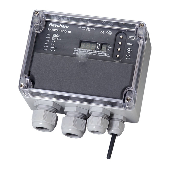
Description RAYSTAT-ECO-10 is an electronic controller with display, advanced alarm facilities and the capability of switching large currents. The RAYSTAT-ECO-10 is designed to control heating cable systems. Heat- ing cable can be controlled either directly by the RAYSTAT-ECO-10 or via a contactor. -
Page 7: Functional Description
T sensor Type: 3-wire Pt 100 according to IEC Class B 50 mm x ∅ 6 mm Sensor head: * An external Pt 100 sensor can be connected, the sensor cable can be extended with a 3-core shielded cable of 20 Ω max. per conductor (e.g. up to 150 m with a 3 x 1.5 mm cable) Functional description... -
Page 8: Installation Description
There are 4 different display modes possible: 1. In the normal operation mode (no error condition), the measured temper- ature or the set point temperature value are displayed in the value display (alternating). During the time that the actual measured temperatures is shown, the T LED in the status display lights up. - Page 9 2. Mounting of the enclosure The RAYSTAT-ECO-10 can be installed indoor or outdoor. Do not install the thermostat under the thermal insulation. A. Wall mounting Mount the enclosure using wall fasteners (screws) via the four, 4 mm ∅ holes. B. Mounting on a pipe Tyco Thermal Controls offers different support brackets (not included) to mount the RAYSTAT-ECO-10 on a pipe: SB-100 or SB-101.
- Page 10 4. Installation of the sensor location of the sensor Mount the sensor in a position exposed to normal weather conditions but shielded from direct sunlight. The sensor should not be located against surfaces that are heated from within or may be heated by sunlight. If the RAYSTAT-ECO-10 is located outdoors, the sensor cable may be shatened and the sensor may be mounted directly to the bottom of the housing, but make sure that at least 35 - 40 mm of the sensor extends beyond the gland fitting...
-
Page 11: Operational Description
Operational description 1. Introduction The RAYSTAT-ECO-10 parameters are configured via a menu system. The unit is delivered with a battery so that the operating parameters can be set up without any need for the power supply to be connected. This is useful for setting units on the bench prior to mounting in their working location or on site when power isn’t available. - Page 12 3. Parameters The first parameter to show up during Set-up mode is the Set Point. Other parameters, their default, minimum and maximum values are shown in the below table: Parameter Default Displayed Min. Max. Value Code Set Point (°C) Min. Expected Ambient (°C) –20 –30...
- Page 13 4. Errors RAYSTAT-ECO-10 can differentiate between 5 errors. The error is displayed as soon as the error condition is detected. The alarm relay switches at the same moment. The value display indicates “ ” (flashing) and the status display indicates the error number. Error Code Description Remedy...
-
Page 14: Testing, Commissioning And Maintenance
Testing, commissioning and maintenance Test heating cable when thermostat installation is complete as directed in the instructions applicable for the heating cable. Fill out the commisioning sheet (page 3514). Maintain thermostat during normal plant maintenance. Check: Mounting is firm Exposed sensor cable is not damaged Glands are tightened firmly Thermostat operation is correct (no error code displayed) Thermostat settings suits application... -
Page 15: Beschreibung Und Technische Daten
Beschreibung Das elektronische Steuergerät RAYSTAT-ECO-10 ist mit einem digitalen Dis- play und umfassenden Alarmfunktionen ausgestattet. Es wurde speziell für die Begleitheizsysteme entwickelt und ist für hohe Belastungen ausgelegt. Das Heizband kann entweder direkt über das Steuergerät oder einen Leis- tungsschütz geschaltet werden. Bei einem Schaltstrom von max. 25 A ist eine Schaltung über den Thermostaten zu empfehlen. -
Page 16: Funktionsbeschreibung
gehäuse Umgebungstemperatur- bereich: –40°C bis +80°C Schutzart: IP65 Bohrungen: 2 x M25, 1 x M20, 1 x M16 Abmessungen: 120 x 160 x 90 mm Gewicht: ca. 800 g Material: Graues Polycarbonat Deckelbefestigung: 4 x M6, Zylinderkpfschrauben - rostfreier Stahl, unverlierbar Montage: Wandmontage oder auf Befestigungswinkel SB-100/SB-101... -
Page 17: Display
Bei einer Störung schaltet das Alarmrelais, und in der Anzeige erscheint eine Fehlermeldung. Sie können außerdem eingeben, ob das Begleitheizsystem bei einem Sensorausfall abschalten oder weiter in Betrieb bleiben soll (EIN oder AUS). Das Steuergerät ist zusätzlich mit einer Batterie (im Lieferumfang) ausgestat- tet, so dass die Programmierung auch ohne Netzspannungsanschluss vorge- nommen werden kann (siehe „Programmierung“... -
Page 18: Montage
Montage 1. heizbandmontage Informationen zur Auswahl und Auslegung von Frostschutzsystemen in der Bautechnik finden Sie in unserem Technischen Handbuch. Eine detaillierte Auswahlhilfe für industrielle Begleitheizsysteme von Tyco Thermal Controls finden Sie in unserer Projektierungsanleitung für industrielle Begleitheizsysteme, bzw. in unserer speziell entwickelten Planungssoftware „TraceCalc“. - Page 19 heizbandanschluss A. Das Heizband kann über einen Anschlußkasten, ein Leistungsschütz oder RayClic mit dem Kaltende des Anschlußmoduls direkt durch die M25-Ver- schraubung 3 angeschlossen werden. B. Das Heizband kann auch direkt im Steuergerät angeschlossen werden. In diesem Fall muss die M25-Verschraubung 3 , die bei der Lieferung bereits am Steuergerät montiert ist, durch eine entsprechende Anschlussgarnitur ersetzt werden (siehe Tabelle S.
-
Page 20: Programmierung
5. Fertigstellung der Montage Bringen Sie die Gehäuseabdeckung wieder an. Wenn Sie das Steuergerät RAYSTAT-ECO-10 noch nicht programmiert haben, folgen Sie nun den Hin- weisen im Kapitel „Programmierung“ auf Seite 20. Schließen Sie den Deckel des Gehäuses. Funktionsbeschreibung 1. Einleitung Die RAYSTAT-ECO-10 Parameter sind über ein System-Menü... - Page 21 Wenn das Steuergerät auf seine Werkseinstellungen zurückgesetzt werden soll, dann drücken Sie gleichzeitig die Tasten + und – für ca. 2 Sekunden. Im Display erscheint anschließend (Default). 3. Parameter Der erste angezeigte Parameter im Display während des Programmiermodus ist die Haltetemperatur. Andere Parameter, Werkseinstellungen, Minimum- und Maximumwerte können aus der folgenden Tabelle entnommen werden.
- Page 22 Fehlercode Beschreibung Abhilfe Sensorkurzschluss (oder Sensor ersetzen sehr geringer Widerstand) Sensorverbindung Sensorkabel anschliessen unterbrochen oder Sensor ersetzen Gemessene Temperatur Messwert überprüfen liegt unter min. Umgebungstemperatur Relaiskontakt schließt Relais defekt/ nicht mehr Einheit ersetzen Versorgungsspannung Spannung überprüfen unter AC 207V Bei potentialfreiem Betrieb wird diese Störung nicht gemeldet. Das Steuergerät schaltet ab, wenn die Versorgungsspannung unter AC 190V fällt.
-
Page 23: Test, Inbetriebnahme Und Wartung
Test, Inbetriebnahme und Wartung Nachdem Sie das Steuergerät montiert haben, prüfen Sie, ob das Heizband ordnungsgemäß funktioniert. Hinweise zur Überprüfung finden Sie in der Montageanleitung des Heizbandes. Nun füllen Sie das Inbetriebnahmeproto- koll aus (Seite 35). Das Steuergerät sollte in regelmäßigen Abständen gewartet werden. Prüfen Sie, ob –... -
Page 24: Description & Caractéristiques Techniques
Description Le RAYSTAT-ECO-10 est un régulateur électronique avec un afficheur, des fonctions d’alarme avancées et la capacité de commuter des courants impor- tants. Il est conçu pour réguler les systèmes de traçage électrique. Le ruban chauffant est commandé soit directement par le RAYSTAT-ECO-10 soit par le biais d’un contacteur. -
Page 25: Fonctionnement
Boîtier Température de service: –40°C à +80°C Protection: IP 65 Entrées: 2 x M25, 1 x M20, 1 x M16 Dimensions: 20 x 160 x 90 mm Poids approx.: 800 g Matériau: polycarbonate Fixation couvercle: 4 vis captives Montage: sur paroi ou support du fixation sur la tuyauterie SB-100 / SB-101 Sonde de température Type:... -
Page 26: Afficheur
En cas d’hésitation à propos du réglage adéquat, il vaut mieux choisir une valeur trop élevée que trop basse pour éviter tout risque de gel des conduites. En cas d’erreur, le relais d’alarme est sollicité et un code d’erreur est donné par l’afficheur. -
Page 27: Installation
Installation 1. Pose du ruban chauffant Pour l’étude et la sélection des rubans chauffants dans les applications bâti- ment, voir le Manuel Technique. Pour les rubans chauffants destinés à l’industrie, voir le Guide de sélection industrie, utiliser la dernière version du logiciel TraceCalc ou encore prendre contact avec votre agent Tyco Thermal Controls. - Page 28 3. Câblage Ôter le capot du terminal pour accéder aux bornes de connexion. Alimentation: Faire passer un câble monophasé (230 Vca) dans le presse-étoupe 2 , taille M25 (schéma A ) et raccorder selon le schéma électrique de la page 37. Raccordement du ruban chauffant: A.
-
Page 29: Paramétrage
Remarque: le câble de la sonde peut être prolongé jusqu’à 150 m avec un câble de section 3 x 1,5 mm . Raccorder cette prolongation dans une boîte de jonction JB-86 ou dispositif équivalent. Utiliser un câble blindé pour éviter les interférences. - Page 30 Pour mettre le thermostat en mode de paramétrage lorsque l’appareil est rac- cordé à l’alimentation électrique (l’afficheur indique alternativement le point de consigne et la valeur de température mesurée), appuyer sur la touche MENU pendant 2 secondes environ. Parcourir la liste complète des paramètres effectués en appuyant successi- vement sur la touche Menu.
- Page 31 Spécifier le diamètre de tuyauterie: 3 pour diam. ≥ 2 pouces 2 pour diam. ≥ 1 pouce 1 pour diam. < 1 pouce 4. Erreurs Le RAYSTAT-ECO-10 est capable d’identifier 5 erreurs. Il affiche l’erreur dès que le problème est détecté, en même temps que s’enclenche le relais d’alar- me.
-
Page 32: Test, Mise En Service Et Entretien
Test, mise en service et entretien Procéder à l’essai du ruban chauffant à la fin de l’installation du régulateur conformément aux instructions de Tyco Thermal Controls concernant le ruban chauffant. Compléter la fiche de mise en service (page 35). Vérifier et entretenir le régulateur lors de la maintenance régulière des installations. -
Page 33: Wiring Diagrams
A. Wiring Diagrams Anschlussdiagramm Schémas électriques R: Same colour R: die gleiche Farbe R: la même couleur * Optional Temp. sensor Pt 100 Heating cable * Optional Temp.Sensor Pt 100 Heizband * Option Sonde de température Ruban chauffant... - Page 34 B. Voltage free operation: Remove links W1 and W2 and change “U” parameter in set up mode from “0” (not volt free) to “1” (volt free) as explained on page 13 of this manual. Potentialfreier Berieb: Entfermen Sie die Brücken W1 und W2 und ändern Sie die den Parameter für potentialfreien Betrieb “U”...
-
Page 36: Commissioning Sheet
Tyco Thermal Controls Norway AS Деловой Центр Кантри Парк Postboks 146 Тел. +7 (495) 926 18 85 1441 Drøbak Факс +7 (495) 926 18 86 Tel. 66 81 79 90 Fax 66 80 83 92 ü www.ze-gmbh.de ZIEGLER ENGINEERING š info@ze-gmbh.de www.tycothermal.com...
Need help?
Do you have a question about the DigiTrace RAYSTAT-ECO-10 and is the answer not in the manual?
Questions and answers