
Summary of Contents for BrainBee multigas 8500
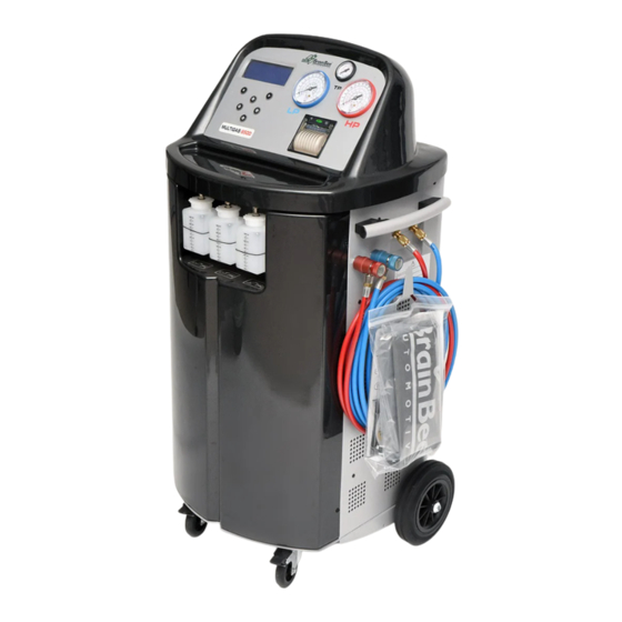
- Page 1 MULTIGAS 8500 Equipment for recharge of air conditioning systems of vehicles with refrigerant gas R-134a/R-1234yf. Service Manual Ver. 1.0...
-
Page 2: Table Of Contents
USE OF THE MANUAL ....................6 SYMBOLS ........................6 4.2.1 Safety ......................6 4.2.2 Marking......................6 CAP. 5 - INSTALLATION......................7 EQUIPMENT INSTALLATION...................7 5.1.1 Unpacking MULTIGAS 8500 ................8 5.1.2 Scale unlocking ....................8 5.1.3 Connections ....................9 5.1.4 Contrast and language setting ................9 5.1.5 Programming ....................9 5.1.5.1 Programming through serial cable .............. - Page 3 MULTIGAS 8500 CAP. 7 - CALIBRATION .....................27 CLIMA 8501 SERVICE KIT FOR STATIONS WITH GAS R134A...........27 CLIMA GAS R-1234YF / R-134A SERVICE KIT FOR STATIONS WITH GAS R134A AND R1234YF ..........................29 PRESSURE CALIBRATION (SERVICE KIT)................31 GAS WEIGHT CALIBRATION (SERVICE KIT) ..............32 OIL WEIGHT CALIBRATION (SERVICE KIT)..............33...
-
Page 4: Cap. 2 - Introduction
R-134a refrigerant gas. The manual chapters describe the functional units of MULTIGAS 8500 under the aspects of structure, operation, disassembly and assistance. To access the service menu reserved to maintenance activities, the technician operating on the device must know the password communicated by Brain Bee to the Assistance Centres. -
Page 5: Cap. 3 - Safety Conditions
MULTIGAS 8500 CAP. 3 - SAFETY CONDITIONS IMPORTANT SAFETY INFORMATION In installation, maintenance and technical assistance operations it is necessary to respect the fundamental staff and workplace safety regulations. Carefully respect all the indications included in this manual, in the device use manual and in the use manuals of any other equipment employed. -
Page 6: Cap. 4 - Layout And Use Of The Manual
MULTIGAS 8500 CAP. 4 - LAYOUT AND USE OF THE MANUAL USE OF THE MANUAL The present service manual must be used together with the use and maintenance manual of the equipment, it must be kept by the Authorised Assistance Centre or by the Distributor of Brain Bee products and made available to own assistance staff. -
Page 7: Cap. 5 - Installation
2° Check the software version and reprogram the equipment if needed 3° Registration of the equipment and data of the end customer on the website www.brainbee.com (distributor reserved area). Registration may also be postponed to after initial checking and it will be proposed again when the database is selected, or every time the equipment is switched on. -
Page 8: Unpacking Multigas 8500
MULTIGAS 8500 5.1.1 Unpacking MULTIGAS 8500 RISK OF OVERTURNING - CRUSHING - BUMPING Position the pallet on a level surface, remove the carton after eliminating the straps that bind it. Free the equipment from the pallet by cutting the straps that block it. Remove the unit from the base pallet of the package by using suitable means. -
Page 9: Connections
PROGRAMMING the CLIMA station with the last version available on the website www.brainbee.com at the time of installation guarantees the installation of the latest versions: •... -
Page 10: 5.1.5.2 Programming Through Acu Device
CLIMA SOLUTION product, install the CLIMA SOLUTION program on a Windows PC connected to the internet. If on the website www.brainbee.com a new version is available, this will be transferred to the PC automatically. Connect ACU to the PC to transfer the new version of the software onto the ACU mobile device. - Page 11 MULTIGAS 8500 ENGLISH 11 / 78 CAP. 5 - INSTALLATION...
-
Page 12: Ec Declaration Of Conformity And Use And Maintenance Manual
MULTIGAS 8500 Until the activation code is entered into the equipment, it will always be requested. 5.1.7 EC declaration of conformity and Use and maintenance manual Deliver the EC Declaration of conformity document attached to the equipment to the client, it will have to be carefully kept by the end customer. -
Page 13: First Tank Filling
MULTIGAS 8500 • Gas weight check (check of scale zero deviation after transport and tare weight reset) • Oils weight check (check of scales zero deviation after transport and tare weight reset) • Pressure check (Reset of relative pressure in relation to the local atmospheric pressure; a tank recharge coupler, supplied with the equipment, must be used) •... -
Page 14: 5.1.9.2 Tracer Container Filling
MULTIGAS 8500 Fill the bottle by paying special attention to the “oil care” valve. This valve is made of a silicon polymer membrane; it compensates pressure variations within the bottle and stops humid air infeed, thus preserving the new oil inside. -
Page 15: Optional Accessories Presentation
5.1.10 Optional accessories presentation The MULTIGAS 8500 station may be equipped with additional accessories such as: 1) the kit for washing the system components (Flushing kit) and 2) the leak searching kit (UV kit) with the tracer and the UV lamp 3) the leak test kit (Nitrogen leak test kit) and 4) the kit to carry out service on hybrid cars (Hybrid pro kit). -
Page 16: Setting Working Parameters And Garage Data
MULTIGAS 8500 5.1.11 Setting working parameters and garage data From the SETUP menu it is possible to select parameters and activations before starting cycles: HYBRID FUNCTION • by selecting this entry, one may change the type of Oil to inject into the A/C system Attention: the HYBRID KIT PRO (optional accessory) is required in order to run this function ECO LOCK®... - Page 17 MULTIGAS 8500 LANGUAGE • by selecting this entry, any language present in the database may be set. In case you choose a language with unintelligible characters, hold down the button in the starting screen- page and you will directly return to the language setting menu.
-
Page 18: Cap. 6 - Maintenance
MULTIGAS 8500 CAP. 6 - MAINTENANCE EQUIPMENT MAINTENANCE The interventions foreseen for periodical and preventive maintenance are listed as follows: • “LONG LIFE PUMP” special function and VACUUM PUMP OIL change • DRYER FILTER replacement (every 45 kg of recovered gas) •... -
Page 19: Vacuum Pump Oil Specifications
MULTIGAS 8500 Place a container under the pump oil drain hole. Open the upper plug and then the lower plug to drain the exhausted oil contained within the vacuum pump. UPPER PLUG SIGHT GLASS LOWER PLUG Once the pump is emptied, rescrew the bottom plug. -
Page 20: Dryer Filter Change
MULTIGAS 8500 These types of oil must ensure: • high viscosity index, which minimizes viscosity variations when temperature changes. This means, in cold conditions, promptness and sensitivity of control and, at the same, time, in warm conditions, stability of operation. - Page 21 MULTIGAS 8500 For replacement, comply with the instructions outlined below: 1. disconnect the HP and LP hoses from other systems/circuits or vehicles and close the quick couplers 2. the unit turns on and empties the hoses. 3. Confirm to have already worn the personal protective equipment (PPE) and follow the safety regulations in force.
-
Page 22: Wear Check Of The Red And Blue Charge Hoses And The Hp Red And Lp Blue Quick Couplers
TESTS of the piping and quick couplers tightness with leak tests under vacuum and under pressure conditions. • Connect the hoses through quick couplers to the false joints on the wall of MULTIGAS 8500 and open the taps/valves; • Launch the “Leak test” function inside the Maintenance Menu, check that the test is passed successfully. -
Page 23: Refrigerant Gas Scale Check With Sample Weight And Calibration, If Needed, (Service Kit)
MULTIGAS 8500 REFRIGERANT GAS SCALE CHECK WITH SAMPLE WEIGHT AND CALIBRATION, IF NEEDED, (SERVICE KIT) Place a sample weight on the tank and check that the changes in weight are adequately detected by the machine scale. Place the clamp that is... -
Page 24: Wear And Tightness Check Of The Manifold Solenoid Valve Pistons
MULTIGAS 8500 WEAR AND TIGHTNESS CHECK OF THE MANIFOLD SOLENOID VALVE PISTONS 1. Apply the 2 pipes in the supports on the side of the machine and close the taps counter clockwise. 2. Switch off the machine, remove the power supply cable and open the cover and the front panel. -
Page 25: Wear Check Of The Or2-106 4.42X2.62 Nbr O-Ring Of The Pressure Sensor Present On The Manifold
MULTIGAS 8500 TEST IN VACUUM Launch the function inside the Maintenance Menu “Leak test”, check that the test is passed successfully. SERVICE MENU - Manual activations WEAR CHECK OF THE OR2-106 4.42X2.62 NBR O-RING OF THE PRESSURE SENSOR PRESENT ON THE MANIFOLD 1. -
Page 26: Presence And Wear Check Of The Or2212
MULTIGAS 8500 17. Once the solenoid valve mounting is complete, reopen the taps/valves of the tank 18. Close panel and cover, reconnect the power supply cable and turn on the machine again. TEST UNDER PRESSURE From the Service Menu “Manual activations”, in relation to the replaced valve, open (activate) or keep closed the solenoid valves represented in the chart reported as follows. -
Page 27: Cap. 7 - Calibration
MULTIGAS 8500 CAP. 7 - CALIBRATION CLIMA 8501 SERVICE KIT FOR STATIONS WITH GAS R134A The service kit is made up of a series of equipment identified as follows, necessary for the programming, calibration and maintenance activities of the CLIMA line equipment. - Page 28 MULTIGAS 8500 Only for CLIMA SUPER 9000; CLIMA-1234-H; CLIMA-1234-HO; for gas weight calibration, use the following 322 g reference weight, assembled as per following instructions: FUNCTION ITEM PROGRAMMING 9. DB9 M/F pin to pin serial cable ZERO PRESSURE 9. Coupler for the recharge of inner tank and for pressure sensors calibration operations, for gas R-1234yf (2 pcs).
-
Page 29: Clima Gas R-1234Yf / R-134A Service Kit For Stations With Gas R134A And R1234Yf
15. Fitting for equipment internal flushing for R-134a quick couplers 16. Fitting for equipment internal flushing for R-1234yf quick couplers NOTE: The sample weight support bracket (4) is suitable for the MULTIGAS 8500; this model does not require the bracket adaptor (14). ENGLISH 29 / 78 CAP. - Page 30 MULTIGAS 8500 Only for CLIMA SUPER 9000; CLIMA-1234-H; CLIMA-1234-HO; for gas weight calibration, use the following 322 g reference weight, assembled as per following instructions: FUNCTION ITEM PROGRAMMING 10. DB9 M/F pin to pin serial cable ZERO PRESSURE 9. Coupler for the recharge of inner tank and for pressure sensors calibration operations, for gas R-1234yf (2 pcs).
-
Page 31: Pressure Calibration (Service Kit)
MULTIGAS 8500 PRESSURE CALIBRATION (SERVICE KIT) From the SERVICE menu, password “BRN”, select the PRESSURE CALIBRATION menu by means of the keys and press Disconnect the LP and HP quick couplers from any A/C system and press Wait for the message asking to connect the tank coupler, included in the clima station accessories kit;... -
Page 32: Gas Weight Calibration (Service Kit)
MULTIGAS 8500 GAS WEIGHT CALIBRATION (SERVICE KIT) From the SERVICE menu, password “BRN”, select the GAS WEIGHT CALIBRATION menu by means of the keys and press Unscrew the tank, lift it and insert below it the spacer bracket in order to keep it detached from the load cell. -
Page 33: Oil Weight Calibration (Service Kit)
MULTIGAS 8500 OIL WEIGHT CALIBRATION (SERVICE KIT) From the SERVICE menu, password “BRN”, select the OIL WEIGHT CALIBRATION menu. Remove the new oil and exhausted oil containers from the equipment and press to acquire the signals of the two loadless oil cells. -
Page 34: Cap. 8 - Gas Type Switching
MULTIGAS 8500 CAP. 8 - GAS TYPE SWITCHING GAS TYPE SWITCHING FROM R134 TO R1234YF When the MULTIGAS 8500 station leaves the factory, it is ready for the gas R134a and can be transformed, by applying the specific kit ( cod. - Page 35 MULTIGAS 8500 CHECK-LIST 1. A/C station inner flushing 2. A/C station emptying 3. Installation of transformation kit 4. A/C station cleaning cycle 5. Gas type setting and vessel charging EQUIPMENT REQUIRED • Brain Bee A/C recovery station or equivalent station for R134.
- Page 36 2) Total emptying of GAS R134a from the station a) Connection between MULTIGAS 8500 and station for gas R134a recovery o Connect the LP coupler of the MULTIGAS 8500 station to the HP coupler of the recovery station, using the R134 MALE HP -> R134 MALE LP COUPLER 14123560010100 o Open HP and LP taps.
- Page 37 MULTIGAS 8500 o vacuum pump output hose o not condensable gas valve output hose o safety valve output hose o fan with rpm control system o 220 V cable o External R-1234yf refrigerant gas bottle fittings and seals ENGLISH 37 / 78...
- Page 38 MULTIGAS 8500 c) Replacement of fan o Remove the old fan of the station and substitute it with the new one inside the kit. o Disconnect the 220V cable (brown and blue) from the switch, from the power board and from the fan.
- Page 39 MULTIGAS 8500 o Connect the new 220 V cable from the switch to the power board switch power board ENGLISH 39 / 78 CAP. 8 - GAS TYPE SWITCHING...
- Page 40 MULTIGAS 8500 o Assemble and connect the new fan and the cable with electronic circuit printer Logic board Logic board “exhaust oil” “pwr prn” Take the pre-assembled fan with metal base with hoses fittings Using the plastic rivets (previously disassembled) assemble the fan...
- Page 41 MULTIGAS 8500 o Assemble the black box to the case of equipment using the cable ties d) Fix the hoses on the fan fittings and connect them to the components below Vacuum Non condensable Safety pump gas valve valve AIR FLOW...
- Page 42 MULTIGAS 8500 e) Disassemble the old fittings and assemble the new ones for R-1234yf quick couplers to the case of the equipment f) Change the old dryer filter as described on service manual and assemble the new one (only if the equipment worked with R134a refrigerant) g) Connect the R1234yf HP &...
- Page 43 Enter the menu “GAS type” o Select R1234 as gas type o Save changes using the password “NGAS” b) Charge the inner vessel of the MULTIGAS 8500 station with gas R1234yf as outlined in the station user manual (at least 3 kg). ENGLISH 43 / 78 CAP.
-
Page 44: Cap. 9 - Update
In order to purchase and activate a new version of the database (included in the A/C station after the software update), REGISTRATION is required, implying the following steps: • access to the distributor reserved area on the website www.brainbee.com • selecting the icon “ACTIVATION AND MANAGEMENT OF DEVICES”... - Page 45 MULTIGAS 8500 Select the serial number by clicking on it, or Start the search procedure through the icon and enter the serial number you searched for. ENGLISH 45 / 78 CAP. 9 - UPDATE...
- Page 46 MULTIGAS 8500 Select update device ENGLISH 46 / 78 CAP. 9 - UPDATE...
- Page 47 MULTIGAS 8500 Enter the database update activation code, which is shown on the A/C station display when you try to access data of a new model present in the databank/database. The confirmation code shown on the website page to avoid counterfeiting.
- Page 48 MULTIGAS 8500 Before confirming, check that the e-mail is correct, otherwise contact Brain Bee sales department. After confirmation you will receive an e-mail (order confirmation) which enables to obtain the code to be entered into the CLIMA equipment to activate the new database version.
-
Page 49: Cap. 10 - Equipment And Simulators
The following equipment is required • CLIMA GAS R-1234YF / R-134A SERVICE KIT FOR STATIONS WITH GAS R134A AND R1234YF • ACU - AUTOMATIC CLIMA UPDATER Software (available on the website http://www.brainbee.it), reserved area • Clima Update Software • Multigas 8500 Software ENGLISH 49 / 78 CAP. -
Page 50: Cap. 11 - Refrigerant Fluid Circuit
MULTIGAS 8500 CAP. 11 - REFRIGERANT FLUID CIRCUIT 11.1 REFRIGERANT FLUID CIRCUIT The chart of the refrigerant fluid circuit of MULTIGAS 8500 is reported as follows. Vessel gauge Vacuum pump Compressor Capacitor fan Refrigerant charge solenoid valve New oil injection solenoid valve... - Page 51 MULTIGAS 8500 Internal refrigerant vessel pressure gauge New and exhaust oil scale Absolute pressure sensor -1 …+35 bar Automatic mechanical expansion valve Heat exchanger Mechanical no return valve Mechanical no return valve Heating belt Accumulation receiver safety valve (20 bar)
-
Page 52: Operational Cycles
MULTIGAS 8500 11.2 OPERATIONAL CYCLES The equipment enables, with a single series of operations, to recover and recycle the refrigerant fluids without dispersions in the environment, also removing humidity and various deposits contained in the oil from the A/C system. - Page 53 MULTIGAS 8500 RECOVERY ENGLISH 53 / 78 CAP. 11 - REFRIGERANT FLUID CIRCUIT...
- Page 54 MULTIGAS 8500 VACUUM ENGLISH 54 / 78 CAP. 11 - REFRIGERANT FLUID CIRCUIT...
- Page 55 MULTIGAS 8500 OIL/TRACER INJECTION ENGLISH 55 / 78 CAP. 11 - REFRIGERANT FLUID CIRCUIT...
- Page 56 MULTIGAS 8500 RECHARGE ENGLISH 56 / 78 CAP. 11 - REFRIGERANT FLUID CIRCUIT...
- Page 57 MULTIGAS 8500 NON-CONDENSABLE GASES DISCHARGE ENGLISH 57 / 78 CAP. 11 - REFRIGERANT FLUID CIRCUIT...
-
Page 58: Receiving Tank
MULTIGAS 8500 11.3 RECEIVING TANK The tank is the component which determines the category of the entire equipment according to the PED directive. The PED “Pressure Equipment Directive” 97/23/EC defines and regulates all those parts that are subject to pressure, with a specific ratio between their pressure and volume. -
Page 59: Manifold Chart
MULTIGAS 8500 11.4 MANIFOLD CHART The manifold chart, where the identification letters of the sectioning valves are highlighted, is reported as follows: • V = vacuum; • A = recovery; • I = interception (HP side and LP side separation);... - Page 60 MULTIGAS 8500 Tracer New oil Vacuum Recovery Interception Vessel pressure Tracer New oil HP/LP Vacuum Recovery gauge Recharge ENGLISH 60 / 78 CAP. 11 - REFRIGERANT FLUID CIRCUIT...
-
Page 61: Suction Unit Chart
MULTIGAS 8500 11.5 SUCTION UNIT CHART The suction unit is a group made up of various pressurised equipments interconnected through brazed piping, which according to the PED directive fall under article 3 paragraph 3. A routine maintenance operation is the replacement of the dryer filter, the procedure of which is outlined in the user manual. -
Page 62: Cap. 12 - Non-Permanent Junctions
MULTIGAS 8500 CAP. 12 - NON-PERMANENT JUNCTIONS Here below some instructions on the use of Loctite® 577 on the thread of some non-permanent junctions in the pneumatic circuit of the CLIMA stations. The product polymerizes when air is absent and when in contact with metal; its aim is preventing slackening caused by impacts and vibrations. -
Page 63: Cap. 13 - Electrical Connections
MULTIGAS 8500 CAP. 13 - ELECTRICAL CONNECTIONS Here below the electric connection diagram of the MULTIGAS 8500 station, with connections between the main components and the printed circuit boards included in the equipment. ENGLISH 63 / 78 CAP. 13 - ELECTRICAL CONNECTIONS... - Page 64 MULTIGAS 8500 Detail of the connectors connecting to the load cells (gas, new and exhausted oil) and the pressure sensor. Connections between power board and actuators on the manifold. ENGLISH 64 / 78 CAP. 13 - ELECTRICAL CONNECTIONS...
-
Page 65: Cap. 14 - Spare Parts
On www.brainbee.com spare parts website, the complete list is available with codes to order them. Enter the reserved area with your dealer username and the Password received from the Brain Bee Sales Department. - Page 66 MULTIGAS 8500 ENGLISH 66 / 78 CAP. 14 - SPARE PARTS...
- Page 67 MULTIGAS 8500 Enter the “Spare parts management” area Select the area of the CLIMA/air conditioning product line and model. Download the document of the chosen model. For the correct display of the spare parts you need to have Acrobat Reader and the appropriate NetSpares Plugin available for installation after download.
-
Page 68: Cap. 15 - Replacement Interventions
MULTIGAS 8500 CAP. 15 - REPLACEMENT INTERVENTIONS 15.1 EXTRAORDINARY MAINTENANCE LIST SERVICE OPERATION DESCRIPTION Vacuum pump replacement Vacuum pump oil replacement Replacement of PNEUMATIC SUCTION UNIT, which includes Mechanical expansion valve Distiller receiver Compressor Compressor oil restore separator receiver Heat exchangers... -
Page 69: Extraordinary Maintenance
MULTIGAS 8500 15.2 EXTRAORDINARY MAINTENANCE 15.2.1 Replacement of components connected to refrigerant circuit The equipment contains parts subject to directive PED Pressure Equipment Directive 97/23/EC. The components (pressurised equipment) constituting/connected to the refrigerant fluid circuit through permanent junctions, such as sealing or brazing, can in no way be disassembled, replaced, changed or handled. - Page 70 Reprogram the machine with the updated software. o Before starting programming through the CLIMAUPDATE programming software (available in the reserved area of the website www.brainbee.com), the type/model of the CLIMA station (Machine Type) shall be set on the printed circuit board received as spare part.
-
Page 71: Replacement Of Electronic Power Board
MULTIGAS 8500 Select the machine type in the pull-down menu Reprogram the machine with the updated software (ref. Chap. 5.1.5.1) • Select the language • Carry out gas scale calibration • Carry out new and exhausted oil scale calibration •... -
Page 72: Cap. 16 - Trouble Shooting
MULTIGAS 8500 CAP. 16 - TROUBLE SHOOTING MALFUNCTION POSSIBLE CAUSE POSSIBLE SOLUTION 1. If the “SD card not present” SD card absent or not 1. Insert or check SD card message is shown during switch mounted well. insertion. on and/or during software 2. - Page 73 MULTIGAS 8500 The solution is keeping to the 20 minutes vacuum time. 8. The gas scale appears Loading cell locking screw Further unscrew the locking screw blocked on a certain value. not sufficiently unscrewed. of the cell, ensuring that it is not in contact with the cell during use.
-
Page 74: Cap. 17 - Diagnostics
MULTIGAS 8500 CAP. 17 - DIAGNOSTICS 17.1 FAILURES LIST Please find below the list of message and alarm codes that could be detected by the MULTIGAS 8500 software. If there are alarms, it is advisable to apply to your supplier or service Partner. - Page 75 MULTIGAS 8500 CODE MESSAGE When it occurs Possible Actions situations W036 FURTHER OIL During oil Insufficient Increase the vacuum INJECTION NOT injection phase vacuum level phase time, check the POSSIBLE A/C system tightness. W044 VESSEL EMPTY During flushing Gas level is too...
- Page 76 MULTIGAS 8500 Alarm messages are coded Axxx in the window title bar. Alarms immediately terminate the procedure and prevent its resumption. CODE MESSAGE When it can Possible causes Actions occur A000 EEPROM NOT In case of Eeprom Change the logic electronic...
- Page 77 MULTIGAS 8500 CODE MESSAGE When it can Possible causes Actions occur A033 CIRCUIT LEAKAGE During Leakage in the Identify the leak position in vacuum, circuit or in the the vehicle or connected vessel vehicle fittings. system and have it recharge or...
- Page 78 MULTIGAS 8500 CODE MESSAGE When it can Possible causes Actions occur A043 VESSEL FULL During the Internal tank full, Decrease quantity of gas gas recovery maximum by filling (injecting) an and hoses capacity level external tank rated for emptying reached...
Need help?
Do you have a question about the multigas 8500 and is the answer not in the manual?
Questions and answers