Table of Contents
Advertisement
Quick Links
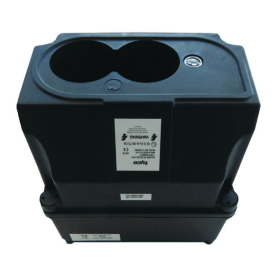
IR6003/7
IR Oil Mist/Smoke Detector
The IR6003/7 Oil Mist/Smoke Detector
has been specially designed to be highly
sensitive to the presence of oil & kerosene
mists or smoke particles in the path of the
detector beam.
The detector has been developed for use in enclosed
oil rig well head areas, generator rooms and turbine
enclosures. The detector automatically compensates for
contamination of the detector lenses and signals when
a point is reached where further deterioration cannot be
tolerated and the lense requires cleaning.
Two levels of alarm status are provided. A low level alarm
and a high level alarm. There is also a beam blocked
status provided in the event that the beam is interrupted.
The detector is intended to be used together with our
P-UIM 6005/2 which will provide the detector as volt-free
contacts.
Features
• Automatic Self Calibration
• Range = 2-30 metres
• Weatherproof to IP65
• Certified Intrinsically Safe EEx ib IIB T5
• Robust Design
• Heavy Duty Mounting Bracket available
• Independent beam blocked output
• Cleaning status output
• Dual automatic compensation
Advertisement
Table of Contents

Related Manuals for Johnson Controls IR6003/7


Summary of Contents for Johnson Controls IR6003/7
- Page 1 IR6003/7 IR Oil Mist/Smoke Detector The IR6003/7 Oil Mist/Smoke Detector Features has been specially designed to be highly sensitive to the presence of oil & kerosene • Automatic Self Calibration mists or smoke particles in the path of the • Range = 2-30 metres detector beam.
- Page 2 IR6003/7 IR Oil Mist/Smoke Detector Functional Description Initialisation: Alarm Level Detection: Dual Automatic Compensation: When the detector is switched on, its The detector monitors the obscuration The detector automatically compensates LED indicator blips on to signify power level within the beam path and when it for gradual detector lens contamination up. During the first 10 seconds the detects a loss of 0.5 dB it latches a low and also compensates for the more rapid detector performs auto calibration to level alarm condition. If the loss is environmental changes (eg. Temperature establish the quiescent obscuration level. maintained within the 0.5 to <1.5 dB Change). The detector will report a clean band during the subsequent 15 second fault (LED Flashes on for 4 seconds) Please note: It is important that the once. If the detector is not cleaned it will beam path is cleared to a healthy state alarm monitoring period, a low level (no obscuration) prior to resetting the alarm will then be reported (LED will continue to operate until a life fault is detector. If the beam path is not healthy, pulse On/Off for 30 seconds). If the loss...
- Page 3 IR6003/7 IR Oil Mist/Smoke Detector Distance Reflector Size Type 2 to 10 M 0.6 x 0.6 M (1 x 6 M x 0.6 M) 10 to 30 M 1.2 x 1.2 M (2 x 1.2 M x 0.6 M) This diagram shows the detector connected to a local junction box via the flying lead (01-33-14). The local junction box will require connecting to our P-UIM For details on how to mount the detector via a suitable safety barrier which refer to heavy duty mounting bracket provided the necessary detector to user Datasheet (01-33-24) equipment interface. (For details see Power UIM 6005/2 Datasheet 01-33-22) Commissioning Operational Parameters 1. The detector LED blips On briefly as it receives power from the P-UIM. The Once the detector has been installed P-UIM Life indicator is flashing. The detector receives its DC supply from correctly by connecting it to the hazard 2. Also Output On indicator should be the P-UIM and provides status reports to monitoring system via the P-UIM, the On steady, all other indicators are the P-UIM as follows: user should power up the detector loop extinguished.
- Page 4 IR6003/7 IR Oil Mist/Smoke Detector SIRA Cert IECEx SIR 14.0009X Technical Specificaions II2 G Ex ib IIB T5 Gb Electrical: Accesories Operating Voltage: 24 V (via P-UIM) Quiescent Current: 25 mA Flying Lead: 01-33-14 Alarm Current: 80 mA (max) Reflector Type 1: 01-33-05 Beam Length: 2 to 30 metres Reflector Type 2: 01-33-10 Reflector Type 3: 01-33-11 Mechanical: P-UIM: 01-33-22 Dimensions: W165 x H125 x D165 mm 0-20 mA Adapter: 01-33-22A Weight: 0.96 kg Heavy Duty M/B: 01-33-24 Material:...
- Page 5 IR6003/7 IR Oil Mist/Smoke Detector Ex Requirements Flying Lead Connections In order to maintain the EEx certified status of the equipment the following requirements must be met: • T he apparatus cannot be repaired and must be replaced by an equivalent unit. • The apparatus is not intended to be exposed to dust conditions. • The equipment when installed in accordance with the instruction manual will not be subjected to mechanical stress. • The equipment should not be installed where it may be subjected to mechanical and thermal stress or where it may be attacked by existing Clients View of Connector or foreseeable aggressive substances. Client List Number Name General Count Number...
- Page 6 IR6003/7 IR Oil Mist/Smoke Detector There are many other companies who integrate our oil mist detection equipment into there safety systems, These can range from: - Heavy Industrial Areas e.g. Engine Rooms - Hazardous Areas - Warehouses - Marine Applications - Oil Rigs - FSPO’s e.g. Shell BONGA - Turbines - Hyraulic Power Units - Plus many more…… © 2019 Johnson Controls. All rights reserved. All specifications and other information shown were current as of document revision date and are subject to change without notice. PSF303JC Issue – 1 08/19 www.johnsoncontrols.co.uk...
Need help?
Do you have a question about the IR6003/7 and is the answer not in the manual?
Questions and answers