
Subscribe to Our Youtube Channel
Related Manuals for Software Bisque Paramount Taurus

Summary of Contents for Software Bisque Paramount Taurus
- Page 1 Paramount Taurus Equatorial Fork Mount Assembly Instructions Software Bisque Inc. Revision 1.4 May 2018 P a g e...
- Page 2 Packing and Screw List Below is a list of the items you will need to install the Taurus Equatorial Fork Mount. There are six boxes containing each component, there are 37 bolts and wrenches you will need to install the Taurus. Picture Description (Taurus 500/600 top, Taurus 400 bottom)
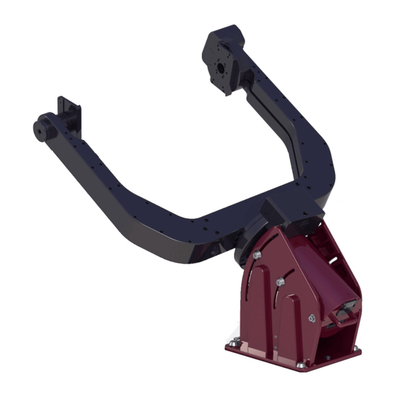
- Page 3 Picture Description (Taurus 500/600 top, Taurus 400 bottom) Wedge Assembly RA Assembly P a g e...
- Page 4 Picture Description (Taurus 500/600 top, Taurus 400 bottom) Fork Base Fork Extension* (2 pieces) * Included with the Taurus 600 that will carry wider OTAs. Fork With Gear P a g e...
- Page 5 Picture Description (Taurus 500/600 top, Taurus 400 bottom) Fork Without Gear Screw List Lock nut (8 pieces) ½-inch-20 x 1-1/2-inch SHCS (Taurus 500/600) 3/8-24 x 1-1/2-inch SHCS (Taurus 400) P a g e...
- Page 6 Azimuth Adjustment Anchor (1 piece) RA and Azimuth Adjustment Shoulder Bolts with washers (3 pieces) Fork Arm Attaching Bolts (12 pieces) ½-inch-13 x 1-1/4-inch SHCS (Taurus 500/600) 3/8-16 x ¾-inch SHCS (Taurus 400) Fork Base Attaching Bolts (8 pieces) ½-inch-13 x 4-1/2-inch SHCS (Taurus 500/600) ½-13 x 3-inch SHCS (Taurus 400) P a g e...
- Page 7 Assembly Instructions Step 1: Mounting Wedge Assembly to the Pedestal Place the wedge assembly on the pedestal in the orientation shown in Figure 1 with the shoulder bolt on the back side of the pier when the pier appears to be tilted away from you. Install the azimuth adjustment shoulder bolt first.
- Page 8 Step 2: Installing RA Assembly into Wedge Assembly Lift the RA tube assembly up into the wedge assembly in the orientation shown in Figure 2. The stainless-steel parts protruding from the tube can be set into a cradle shown again in Figure 2. Once in the cradle, the wedge can hold the weight of the RA assembly but is free to rotate within the wedges.
- Page 9 Equal distances. Figure 3: Altitude adjustment stainless-steel bar at the mid-travel position. Figure 4: Altitude adjuster install position. Once the altitude adjustment bar is in place and it is lowered to a manageable height, then the RA shoulder bolts should be installed. The stainless steel threads in the tube will need to be lined up with the shoulder bolt area on the wedges so using the handle on the back of the RA assembly is helpful to get the holes central while screwing in the shoulder bolts.
- Page 10 Two Lock nut and bolts; two more located on the opposite side of the mount. Shoulder Bolt; One on opposite side of the mount. Figure 5: Shoulder bolt and wedge attaching bolts. Step 3: Installing Fork Base Fork Base Installation If the RA assembly isn’t lowered to a manageable height to install the fork arms, the RA assembly can also be more easily lowered before the next step of the installation.
- Page 11 Figure 6: Installing fork base (locking bolts in blue). Fork Extensions Installation For some larger scopes, fork base extensions are needed. There is one for each side of the fork base and are installed with six ½-inch-13 x 1-1/4-inch SHCS, three on each side (top and bottom). Both parts are identical, so orientation is determined by lining up the cabling passages before installing the screws.
- Page 12 Figure 7: Installing fork base extensions. Step 4: Installing Fork Arm without Gear The fork arms have to be on a certain side of the mount, so start with the fork arm without the gear. This one has just a rotating cylinder and no gear or drive system with cables and therefore will be a little lighter than the arm with the gear.
- Page 13 Figure 8: Installing fork without gear (fork base extensions not pictured). Installing Fork Arm with Gear Install the second arm just as the first ensuring that the cables coming from the Declination axis are hanging out of the way and don’t get pinched anywhere. Screw in at least the top three 3/8-16x3/4-inch SHCSs as shown in Figure 9.
- Page 14 In order to have access to the MKS 5000 printed circuit board (PCB) and L-Com plate, the rear top plate can be removed. When installing the standard Software Bisque cables it is easiest to remove the entire rear top plate. There are four ¼-inch-20 screws holding the plate on (see Figure 10). Once removing the top plate, you can see the MKS 5000 PCB and the RA shaft (see Figure 11).
- Page 15 There are either two or three cables coming out of the declination axis on the fork with gear depending on if the mount has encoders. The sensor cable is a 4-wire ribbon cable with a black connector. The motor extension cable is two grey cables with a large white connector. And last, the encoder cable is a single dark grey cable with a small white connector, labeled “Dec”.
- Page 16 Figure 14: Right Ascension encoder cable strain relief. The declination encoder cable also needs to be installed into the strain relief to keep the fragile wires from being pulled on. To do this you pull the elastic out of the plastic connector channel then wrap it around both cables and insert the elastic back into the channel (see Figure 15).
- Page 17 All the cables coming from the declination axis can then be “stuffed” into the cable channel the whole way down. The cable channel is shown in Figure 16 for the standard Software Bisque cables. The other arm has a matching channel that can be used for individual system wiring.
- Page 18 Figure 17: RA shaft for running cables. 18 | P a g e...
-
Page 19: Altitude Adjustment
Altitude Adjustment Step 2: Installing RA Assembly into Wedge Assembly, it is described how to lower the altitude adjustment during installation. This is also true for when the Taurus is completely assembled and can be aided with a rope or bungee cable so no one has to be underneath the mount while it is being lowered. In order to raise the altitude adjuster, it is easiest to have two people, one on each arm lifting up to raise it to the perspective major altitude slot. -
Page 20: Appendix A: Revision History
Addition or Change • Paramount Taurus 500/600 Equatorial Mount Assembly Instructions. • Paramount Taurus 400 Assembly instructions now included. • Added instructions to install fork base extensions which are required for larger telescopes on the Taurus 600. • Minor grammatical corrections.
Need help?
Do you have a question about the Paramount Taurus and is the answer not in the manual?
Questions and answers