Table of Contents
Advertisement
Quick Links
Advertisement
Table of Contents

Summary of Contents for Bartington SCU1
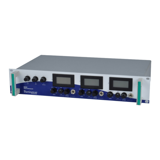
- Page 1 Operation Manual for SCU1 Signal Conditioning Unit...
-
Page 2: Table Of Contents
4. Introduction to the SCU1 4.1. Summary 4.2. Functional Description 4.2.1. Power 4.2.2. Signal Conditioning 5. SCU1 Inputs, Outputs and Controls 5.1. Back Panel Connections and Controls 5.2. Front Panel Displays and Controls 6. Installing the SCU1 6.1. Location of the Equipment 6.1.1. - Page 3 7.4. Using the SCU1 Controls 7.4.1. Offset Controls 7.4.2. Gain Controls 7.4.3. Low Pass Filter (LPF) 7.4.4. High Pass Filter (HPF) 7.5. Using the SCU1 Outputs and Displays 7.5.1. Unconditioned and Conditioned Outputs 7.5.2. Display Panel Meters 8. Troubleshooting 9. Care and Maintenance 9.1.
-
Page 4: About This Manual
This manual provides the information necessary to help customers operate the SCU1 Signal Conditioning Unit from Bartington Instruments. It should be read in conjunction with product brochure DS2519, which can be found on the SCU1 product page on the Bartington Instruments website at: www.bartington.com. -
Page 5: Compatible Magnetometers
BARTINGTON INSTRUMENTS 3. Compatible Magnetometers The SCU1 is designed to be compatible with the sensors shown on the Product Compatibility page of the Bartington Instruments website at: www.bartington.com/product-compatibility.html. Caution: Use of incompatible sensors may cause damage to the SCU1 and/or the sensor. - Page 6 The conditioned output signals and the original magnetometer (unconditioned) output signals are available as analogue voltages from the SCU1. In addition, the DC components of each conditioned signal are displayed digitally on display meters. Page 6 of 19...
-
Page 7: Scu1 Inputs, Outputs And Controls
1. Unconditioned Outputs. These three BNC connectors provide buffered versions of the X, Y and Z output signals from the magnetometer. Signals are only valid when the SCU1 is switched ON. They are not affected by any of the other SCU1 controls. -
Page 8: Front Panel Displays And Controls
This control sets the -3dB point frequency for the LPF. Note: The LPF cannot be completely disabled. 8. High Pass Filter (HPF) Control. The SCU1 can apply high pass filtering to the magnetometer output signals. This control sets the -3dB point frequency for the HPF. - Page 9 BARTINGTON INSTRUMENTS 11. Offset Switches (one for each channel). These 3-position switches control the polarity of the offset DC voltages applied to the magnetometer output signals (see Table 1 below). There is an individual switch for each of the X, Y and Z channels.
-
Page 10: Installing The Scu1
• out of direct sunlight. 6.1.5. Proximity to Other Equipment The SCU1 contains no high frequency electronics likely to cause emissions which could cause interference with other equipment. The unit is unlikely to be affected by interference from other equipment in the normal operating environment. -
Page 11: Connecting The Equipment
The locking ring should be hand-tightened only. 2. If your system will use the SCU1 analogue outputs, connect the conditioned and/or unconditioned BNC outputs to your external equipment, as required. 3. Ensure the IEC socket mains switch (Figure 1, item 5) is OFF (position 0). Connect your mains supply cable to the IEC socket. -
Page 12: Using The Scu1
For example, if the display for the X axis shows 6.5V when connected to a magnetometer with a range of 250μT and an analogue output of ±10V, with SCU1 gain = 50, this indicates an X axis field (6.5/50) x (250/10) = 3.25µT 7.2. -
Page 13: Switching On And Off
Similarly, switch off the SCU1 before disconnecting the magnetometer. Caution: The SCU1 should be switched on and off using the IEC socket switch (Figure 1, item 4) (“0” = OFF, “1” = ON). -
Page 14: Low Pass Filter (Lpf)
7.4.3. Low Pass Filter (LPF) The LPF attenuates high frequencies above the -3dB setting, reducing their amplitude in the SCU1 conditioned outputs. The LPF is intended to be used for removal of unwanted frequencies present in the magnetic field being measured. -
Page 15: Using The Scu1 Outputs And Displays
7.5.1. Unconditioned and Conditioned Outputs The SCU1 analogue outputs should be used when both the AC and DC content of the signals need to be measured (e.g. with an oscilloscope, meter or an A-to-D system) or when a voltage output is required for connection, for example, to a feedback or control system. -
Page 16: Troubleshooting
(strictly, frequencies below 1Hz) present in the conditioned output voltage. 8. Troubleshooting The SCU1 is unlikely to suffer any defects in normal use: no internal components are serviceable. The most likely causes of failure, and their solutions, are detailed in the following table. -
Page 17: Care And Maintenance
BARTINGTON INSTRUMENTS 9. Care and Maintenance The SCU1 requires no routine maintenance. The only user serviceable parts are the fuses in the IEC mains inlet socket. 9.1. Fuses To change a blown fuse, ensure the mains supply is disconnected, then extract the fuse block from the IEC socket with a blunt tool (e.g. -
Page 18: End Of Life Disposal
BARTINGTON INSTRUMENTS 10. End of Life Disposal This product (electrical and electronic equipment) should not be placed in municipal waste. Check local regulations for disposal of electronic products. Notes Page 18 of 19 OM2441/1... - Page 19 The copyright of this document is the property of Bartington Instruments Ltd. Bartington® is a registered trade mark of Bartington Instruments Limited in the following countries: United Kingdom, Australia, Brazil, Canada, China, European Union, India, Japan, Norway and the...