Table of Contents
Advertisement
Quick Links
Instruction Manual
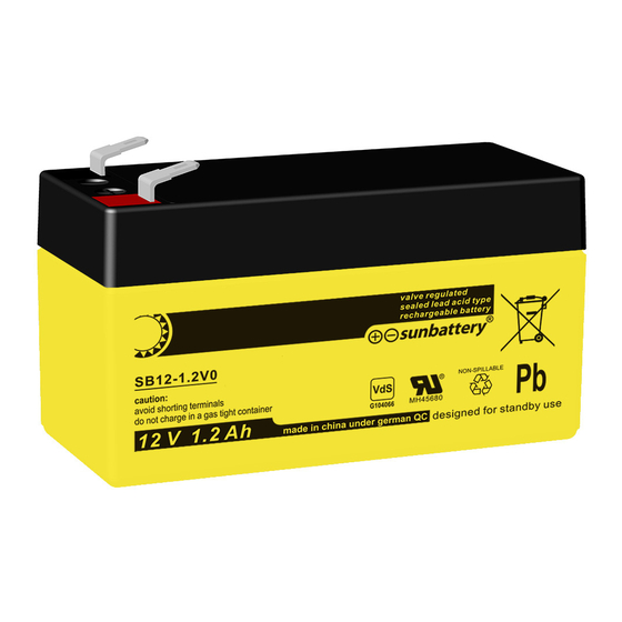
Maintenance-free lead acid batteries in valve regulated lead acid.
Nominal values
• Nominal voltage U
:
N
• Nominal capacity C20
• Nominal temperature T
:
N
• Reduction factors:
• Nominal discharge: I
= I
N
20
Battery manufacturer: SUN Battery
Assembled by:
Installation by:
Safety markings by:
●
Refer to the instruction manual and keep it in a visible place near to the batteries!
●
Only carry out works to a battery under supervision from qualified staff!
●
Smoking prohibited! To avoid the risk of fire and explosions, keep naked flames, sparks
and burning/glowing materials away from the battery!
●
When working on batteries, wear safety goggles and protective clothing!
●
Take note of the accident prevention regulations, such as EN IEC 62485-2!
●
If acid sprays onto the eye or skin, rinse it off with plenty of clean water. Then contact a
doctor immediately. Wash any clothing that has come into contact with acid in water!
●
Risk of fire and explosions! Avoid short circuits! Attention! A battery's metal parts are
subject to constant voltage, so do not put foreign objects or tools on the battery!
●
Electrolyte is highly corrosive! In normal operating conditions, there is almost no risk of
coming into contact with the electrolyte. If you do come into contact with the electrolyte,
contact a doctor immediately!
●
Battery blocks / cells are heavy, even when empty!
Make sure they are solidly installed!
●
Only use suitable means of transport.
●
The guarantee is void if the instruction manual is not observed, if non-original parts are
used for repair, or if you undertake invasive repairs yourself.
●
Returns to the manufacturer!
Used batteries bearing this sign are a recyclable item and must be recycled. Used bat-
teries that are not recycled must be disposed of as hazardous waste in full accordance
with the regulations.
Sealed lead batteries consist of cells that do not need
to be filled up with water for their entire working lives.
Pressure relief valves function as plugs, and any at-
tempt to open them will cause damage.
1. Before Service
Before being brought into service, all banks should
be checked: for mechanical damage; that the pola-
rity is correct; and that the connectors are firmly at-
tached. The following torque settings apply to screw
connectors.
M5
M6
M8
2-3 Nm
4-5,5 Nm
5-6 Nm
2. Operation
Refer to EN IEC 62485-2 for operating and installa-
tion guidelines for these batteries. The battery should
be installed to avoid temperature shifts of > 3K.
2.1 Discharge
Do not discharge the battery below its cutoff voltage
for its designated discharge current. Unless the ma-
nufacturer specifies otherwise, do not draw more than
the nominal capacity. After discharge – even partial
discharge – the battery must be charged immediately
(it may be necessary to lift the pole covers). Before
charging the battery, make sure the charger is turned
off, polarity is correct (positive pole connected to the
positive connector) and separate loads are connec-
ted to a direct current power source. Turn the charger
on and begin charge as follows in point 2.2.
2 V Cells 6 V Blocks 12 V Blocks
20 hr discharge
25°C
as per EN IEC 62485-2
C
/20h
N
Type: SUN
2.2 Charging
All charging procedures where the maximum and
minimum values correspond to DIN 41773-1 (IU
Kennlinie) may be used. Depending on the make of
the charger used and its charging curve, alternating
currents superposed to the direct current may flow
through the battery (< 0.1 C(A) ripple factor). The su-
perposed alternating currents and the contrary action
of loads can cause the battery to heat up abnormal-
ly and put additional strain on the electrodes – and
cause possible damage (see point 2.5). Depending
on the battery set-up, the following charging methods
M10
can be used (corresponding to VDE 0510-485-2).
Batteries are not allowed to be charged upside down!
14-22 Nm
a) Continuous parallel supply and buffer supply.
In this case, the loads, direct current source and
battery are continuously connected in parallel. At the
same time the charging voltage is equal to the batte-
ry's operating voltage and installation voltage. In con-
tinuous supply, the direct current source can always
supply the maximum load current plus the battery
charging current. The battery only supplies electricity
if the direct current source fails. The correct charging
voltage is 2.275 V ± 0.005 V (25°C) x the number of
cells connected in series, measured at the battery's
Storage duration in relation to the
date of manufacture.
Less than 9 months
Up to a year
1 to 2 years
terminal posts. In the case of buffer charging, the di-
rect current source is not able to supply the total load
current at any time. There are times when the load
current exceeds the nominal current of the direct cur-
rent source. During these times, the battery supplies
power. It is not always fully-charged, though the float
voltage of 2.275 V/cell (25°C) x the number of cells
is sufficient to ensure recharge in a series connec-
tion. A load-and-cell-quantity-dependent calibration
should be provided, in any specific instance, by the
manufacturer.
on:
on:
b) On-off operation
Whilst being charged, the battery is disconnected
on:
from its load. To decrease recharging time, the batte-
ry can be charged at 2.35-2.40 V during its first char-
ging phase before the charging current is reduced
to 0.07 C(A) (t1). The first charging phase lasts until
this value is reached. In the second charging phase,
a voltage of 2.355-2.40 V/cell is used. The charging
duration of this phase should be 50% of the first
(t2=0.5T1). If the value of t > t1 + 0.5t1 is exceeded,
the charging voltage is reduced to 2.275 V/cell
(± 0.005 V) at 25°C.
c) Battery operation (charging / discharging cycle)
The load is only charged from the battery. The correct
charging procedure depends on the user and should
be clarified with the manufacturer.
2.3 Maintaining full charge (float charging)
Appliances fitting the criteria set out in DIN 41773-1
should be used. They should be set up so that the
average cell voltage is 2.275 V ± 0.005 V.
2.4 Top-up or equalisation charging
To prolong battery life, it is advisable to do a top-up
charge before running the batteries, providing the
batteries have been stored for more than 6 months –
but not longer than 9 months – with reference to the
date of manufacture. The batteries should also have
a terminal voltage of less than 2.1 V/cell. The top-up
charge should be carried out using the values speci-
fied. For batteries retrofitted to form a replacement
battery bank for standard float charging, no equalisa-
tion charging is needed to bring the terminal voltage
in line with the other batteries.
2.5 Superposed alternating currents
In the case of the operating scenarios outlined in
point 2.2, the effective value of the alternating current
can temporarily rise to 0.1 C(A) whilst being rechar-
ged at up to 2.4 V/cell. After recharging and ongoing
charging (float charging) in a continuous battery pow-
er supply or float battery supply, the effective value of
the alternating current should not exceed a nominal
capacity of 2 A / 100 AH.
2.6 Charging currents
In continuous battery supplies and float battery sup-
plies, there is no charging current limit if there is no
recharging stage. The charging current should be 10
to 20 A for every 100 AH of nominal capacity (Bench-
mark).
2.7 Temperature
The recommended operating temperature range for
lead batteries is 10°C to 30°C. The ideal temperature
range is 20°C ±5 (according to EUROBAT). Higher
Charging voltage per
cell at 25°C
2,28 V/cell
2,35 V/cell
2,35 V/cell
1
Charging time
Longer than 72 hours
48 to 144 hours
72 to 144 hours
Advertisement
Table of Contents

Summary of Contents for Sunbattery SB6-1,2
- Page 1 Instruction Manual Maintenance-free lead acid batteries in valve regulated lead acid. Nominal values terminal posts. In the case of buffer charging, the di- • Nominal voltage U 2 V Cells 6 V Blocks 12 V Blocks rect current source is not able to supply the total load •...
- Page 2 1,75 V/Z 1,60 V/Z ging voltage must be recalibrated to the temperature. A power-charging procedure can then be used if a rapid recharge is needed. In this case, the charging SB6-1,2 1,2 Ah 1,12 Ah 1,01 Ah 0,882 Ah 0,728 Ah current should not exceed 0.01 C(A) and constantly...
Need help?
Do you have a question about the SB6-1,2 and is the answer not in the manual?
Questions and answers