
Summary of Contents for Elmos AP11-37
- Page 1 Panel Meter AP 11 Technical documentation U-19 AP11 - 37 - Counter www.apoelmos.cz ISO 9001...
- Page 2 2015, TD-U-19-25 A.P.O. - ELMOS v.o.s., Pražská 90, Nová Paka 509 01 tel. +420 493 504 261, fax: +420 493 504 257, e-mail: apo@apoelmos.cz...
-
Page 3: Table Of Contents
8.6.1 Functional characteristics of limit switches ............24 9 Panel meter menu functions ............... 26 9.1 Functions of buttons in setting mode ............26 9.2 W orking mode ..................26 A.P.O. - ELMOS v.o.s., Pražská 90, Nová Paka 509 01 tel. +420 493 504 261, fax: +420 493 504 257, e-mail: apo@apoelmos.cz... - Page 4 11 ES Declaration of conformity ..............38 12 Certificate of quality and completness ............39 13 Guarantee conditions ................39 A.P.O. - ELMOS v.o.s., Pražská 90, Nová Paka 509 01 tel. +420 493 504 261, fax: +420 493 504 257, e-mail: apo@apoelmos.cz...
-
Page 5: Introduction
INTRODUCTION AP11-37 Counter is 5 digit programmable panel meter for measuring in time dependent current signal.De- vice is controlled with digital signal processor with A/D transducer.Counter is operated with key-board pla- ced on front panel or with control software that is used for setting of all parameters and archiving measu- red values. Panel meter has tobe provided with communication line, variants of communication lines are in ordering code. Control software is included in standard delivery. Counter is equipped with three-colour dis- play allowing for a quick check of limits within measured value oscillates. Visually interesting element is au- xiliary horizontal bargraph. AP11 Counter inputs are assembled for unified outputs from sensors of techno- logical processes (0/4-20 mA, 0/2-10 V).There is an variant with analogue output that can be galvanic separated in panel me- ter ordering code.With multi-stage types of panel meters analogue output can be assigned to any input by a program, eventually to sum. Any of the communication line variants can be used for communication of panel meter with PC.Communication lines RS232 or RS485 (can be galvanic separated) are in ordering code. Com- bination of two communication lines RS232 and RS485 can be used for above standard applications. Com- munication enables not only setting of parameters and data archiving, but regarding the possibility of ad- dressing of individual panel meters it can be also used for interconnection of bigger number of panel me- ters and controlling of complete technological lines. A.P.O. - ELMOS v.o.s., Pražská 90, Nová Paka 509 01 tel. +420 493 504 261, fax: +420 493 504 257, e-mail: apo@apoelmos.cz... -
Page 6: Ordering Code
Example of order code AP 11 - - 2 - 2 - 3 - 1 - 4 - A.P.O. - ELMOS v.o.s., Pražská 90, Nová Paka 509 01 tel. +420 493 504 261, fax: +420 493 504 257, e-mail: apo@apoelmos.cz... -
Page 7: Technical Data
Auxiliary power > 18 VDC @ 25 mA for feeding of sensors supply Max. load of auxiliary power supply 40 mA Outputs Contact 2x relay (switching contact 250 VAC, 2A or 30 VDC, 2A) or 4x relay (switching contact 250 VAC, 2A or 30 VDC, 2A) Analogue 13.5 bit D/A transducer without galvanic separation or with galvanic se- paration current 0 (4) – 20 mA, loading resistance max. 400 Ω voltage 0 – 10 V, loading resistance min. 10 kΩ Communication RS485 without galvanic separation or with galvanic separation, two way communication RS232 without galvanic separation A.P.O. - ELMOS v.o.s., Pražská 90, Nová Paka 509 01 tel. +420 493 504 261, fax: +420 493 504 257, e-mail: apo@apoelmos.cz... - Page 8 Electromagnetic compatibility ČSN EN 61326 Seismic resistibility ČSN IEC 980: 1993, čl. 6 Electric safety ČSN EN 61010-1: 2003 A.P.O. - ELMOS v.o.s., Pražská 90, Nová Paka 509 01 tel. +420 493 504 261, fax: +420 493 504 257, e-mail: apo@apoelmos.cz...
-
Page 9: Panel Meter Description
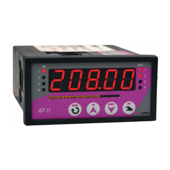
Key „UP“ is used for browsing parameters and setting of numeric data when programming. Pushing and kee- ping down of the key speeds up browsing and setting procedure. - Key „DOWN“ Key „DOWN“ is used for browsing parameters and setting of numeric data when programming. Pushing and keeping down of the key speeds up browsing and setting procedure. - Key „SET“ Key „SET“ is used for setting data, programming termination, data uploading into EEPROM and return to operating mode. - Output „OUT“ indicators Indicators OUT 1 to OUT 4 indicates state of individual outputs in the following manner: indicator flashing – output switched, indicator is not flashing – output is off. A.P.O. - ELMOS v.o.s., Pražská 90, Nová Paka 509 01 tel. +420 493 504 261, fax: +420 493 504 257, e-mail: apo@apoelmos.cz... -
Page 10: Dimensions Of Panel Meter And Assembly Opening
Dimensions for power supply 18 - 36 VDC / 18 - 36 VAC, 50 Hz (fig. 3b) Front view Side view fig. 3b A.P.O. - ELMOS v.o.s., Pražská 90, Nová Paka 509 01 tel. +420 493 504 261, fax: +420 493 504 257, e-mail: apo@apoelmos.cz... -
Page 11: Connection
Reducing of interference influence 4.2.1 Following rules should be observed with designing of the system: a) All power supply conductors and power lines has to be led separately from signal lines (e.g. thermocouple, communication). Min. gap between these types of lines shouldn´t be less than 30 cm. b) If signal line crosses power line they should intersect in right angle. c) Lead the lines out of the potential source of interference. d) Don‘t install relay and contactors too close to panel meter. e) Use twisted and screened conductor for signal line. A.P.O. - ELMOS v.o.s., Pražská 90, Nová Paka 509 01 tel. +420 493 504 261, fax: +420 493 504 257, e-mail: apo@apoelmos.cz... -
Page 12: Connection To Supply Voltage
Feeding voltage ge 80 - 253 VAC, 50 Hz 18 - 36 VDC 18 - 36 VAC fig. 5 A.P.O. - ELMOS v.o.s., Pražská 90, Nová Paka 509 01 tel. +420 493 504 261, fax: +420 493 504 257, e-mail: apo@apoelmos.cz... -
Page 13: Connection Of Input Signals
Requirement of right measuring is necessary to set type of signal input in menu SENS du- ring device configuration. figure.6 A.P.O. - ELMOS v.o.s., Pražská 90, Nová Paka 509 01 tel. +420 493 504 261, fax: +420 493 504 257, e-mail: apo@apoelmos.cz... -
Page 14: Current Signal 4 - 20 Ma
Leaving the device config menu by pressing SET key will save all settings to device EEPROM. 4.4.3 Auxiliary digital inputs fig.9 K1 - contact resets SUM 1 K2 - contact for reseting / seting measured value more on page 35 A.P.O. - ELMOS v.o.s., Pražská 90, Nová Paka 509 01 tel. +420 493 504 261, fax: +420 493 504 257, e-mail: apo@apoelmos.cz... -
Page 15: Pulse Signal Input (Max. 10 Khz)
SENSOR fig. 12 Example connection of sensor with PNP output level. In menu item CONF set the function of pulse input to TOTAL / RATE (coun- ter / frequency-meter), INPUT to PNP and the level of the input comparator TRIG to LOW. SENSOR A.P.O. - ELMOS v.o.s., Pražská 90, Nová Paka 509 01 tel. +420 493 504 261, fax: +420 493 504 257, e-mail: apo@apoelmos.cz... -
Page 16: Analogue Output
0-20 mA 0-20 4-20 mA 4-20 20-0 mA 20-0 20-4 mA 20-4 Voltage 0-10 V 0-20 2-10 V 4-20 10-0 V 20-0 10-2 V 20-4 Options of analogue output connections with or without galvanic separation are shown on fig. 13. Type of output signal is selected in menu with parameter DACO and in its submenu by function AOUT. A.P.O. - ELMOS v.o.s., Pražská 90, Nová Paka 509 01 tel. +420 493 504 261, fax: +420 493 504 257, e-mail: apo@apoelmos.cz... -
Page 17: Block Diagram Of Analogue Output Function
ANALOGUE OUTPUT Block diagram of analogue output function Principle of analogue output is shown on block diagrams Fig. 14 and 15. Diagrams of voltage and current output are separated for better orientation. In real connection are inputs and setup AOUT, ASTR and END common. For currect function of panel meter set range of analogue output ASTR (start of range), AEND (end of range), that relates to input signal – see configuration of start and end of analogue output. Current output fig. 14 Voltage output fig. 15 A.P.O. - ELMOS v.o.s., Pražská 90, Nová Paka 509 01 tel. +420 493 504 261, fax: +420 493 504 257, e-mail: apo@apoelmos.cz... -
Page 18: Communication
Diagram of communication line RS232 connection to PC (connector Canon 9 pin) connector Canon 9 pin fig. 18 obr. 19 A.P.O. - ELMOS v.o.s., Pražská 90, Nová Paka 509 01 tel. +420 493 504 261, fax: +420 493 504 257, e-mail: apo@apoelmos.cz... -
Page 19: Connection Of Contact Outputs
CONNECTION OF CONTACTC OUTPUTS Figure 19 shows options of connections of output relay contacts. Max. load of relay contacts is 250 VAC, 2 A or 30 VDC, 2A. It is advisable to connect antijamming RC cells (e.g. 220 ohm and 0,1 μF) to respective con- tacts to increase reliability and to reduce jamming. State of output relays 1,2,3,4 (if present) select in menu of AP11-37 . The state of relays setup in submenu parameters ALA1 to ALA4. fig. 19 RE 1 RE 2 RE 3 RE 4 (ALA-1) (ALA-2) (ALA-4) (ALA-3) A.P.O. - ELMOS v.o.s., Pražská 90, Nová Paka 509 01 tel. +420 493 504 261, fax: +420 493 504 257, e-mail: apo@apoelmos.cz... -
Page 20: Panel Meter Functions
If LED diode IN 1 flashes panel meter needs to be recalibrated. Panel meter reset Unplug panel meter from power supply. Keep key SET pressed and connect the panel meter to power sup- ply. Keep the key pressed until sign RESET appears on display. Default parameters are restored after reset! A.P.O. - ELMOS v.o.s., Pražská 90, Nová Paka 509 01 tel. +420 493 504 261, fax: +420 493 504 257, e-mail: apo@apoelmos.cz... -
Page 21: Display Setting
Fig. 21 schematically shows principle of colour change in dependence on measured value. In regulator Menu it is necessary to set to which sector (SEC-0, SEC-1 and SEC-2) the particular colour is as- signed (R, G, Y). Then it is necessary to set limits within which the measured value should oscillate. Bottom limit is defined with parameter LO and top limit with HI. With this setting we suppose that required value is located in sector 1 (SEC-1) and if it oscillates within set limits, display flashes in green. If the value falls below LO (sector 0) it starts flashing in yellow and on contrary if measured value rises on the top limit HI display starts flashing in red. Colours assigned to individual sectors SEC-0, SEC-1, SEC-2 can be changed in regulator menu as needed. If you want to change display colour permanently without any relation to mea- sured value set the same colour to all parameters SEC0, SEC1, SEC2 . With requirement for two colour display set only one of two limit parameters LO or HI separating two neig- hbouring sectors and set for one sector e.g. red colour (R) and for remaining two sectors green (G). example: fig. 21 In menu for display properties setting DIS-1, intensity of display light can be set. Scroll to parameter LIGHT in menu. In setting mode display light intensity can be set to 25%, 50%, 75% and 100% with keys UP and DOWN. Change of display light intensity is common for all inputs. Change of display colour according to measured value is always related to selected input! A.P.O. - ELMOS v.o.s., Pražská 90, Nová Paka 509 01 tel. +420 493 504 261, fax: +420 493 504 257, e-mail: apo@apoelmos.cz... -
Page 22: Bargraph
MENU to enter into submenu where confirm parameter BSTR for option the start of baragraph range with pressing key MENU. Set required value with keys UP and DOWN. Press SET key to confirm changes. To set the end of bargraph ran- ge find in submenu BARGf parameter BEND. Setting procedure is identical with BSTR. Choose as the last item for which input are required values set. Find in submenu parameter B-IN. Press key MENU to enter into setting mode and set required input In-1 , In-2, sum-1, sum-2, ala-1 to ala - 4. Press key SET to confirm the setting. E.g. the start of range (BSTR) is 0 and the end (BEND) 200 and measured value shall be on level 100, bar- graph shall indicate to the half of the scale. Bargraph is formed with column 30. of LED diodes. Setting parameter B-IN to ala-1 to ala-4 , bargraph takes configuration parameteres from menu ALA1/ALA2/ALA3/ALA4 ie.B-END is derived from required valueSP. Starting range of bargraph B-S- TR is in this case 0. obr. 22 A.P.O. - ELMOS v.o.s., Pražská 90, Nová Paka 509 01 tel. +420 493 504 261, fax: +420 493 504 257, e-mail: apo@apoelmos.cz... -
Page 23: Functions Of Limit Switch
Functions of limit switches Figure 23. shows connection of inputs to limit switches (ALA1 to ALA4) fig. 23 Relay 1 Relay2 Relay 3 Relay 4 fig.24 ALARM meas. value time output state time A.P.O. - ELMOS v.o.s., Pražská 90, Nová Paka 509 01 tel. +420 493 504 261, fax: +420 493 504 257, e-mail: apo@apoelmos.cz... -
Page 24: Functional Characteristics Of Limit Switches
Setup of switching hysteresis of output relays. hyst EVENT/ACTION -no--no event CL-S1-reset SUM1 ad-s1 -adding to SUM1(+meas.value) su-s1-subbtraction from SUM1(-meas.value) CL-S1-reset SUM 2 AD-s2-adding to SUM1 (+1) SU-S2 -subtraction from SUM2(-1) CL-in-clearing measured value Events take action only if alarm conditions are met. Repeated events occur only if alarm is over Time limit switch Setting of switching time period for output relay TIME value (TRAL set to TIME) A.P.O. - ELMOS v.o.s., Pražská 90, Nová Paka 509 01 tel. +420 493 504 261, fax: +420 493 504 257, e-mail: apo@apoelmos.cz... - Page 25 SET key.Next parametr to be set is HYST(hysteresis). Press MENU key and by pressing UP or DOWN set the requested value.Confirm setting by pressing SET key.Next function is IN parameter.It defines for what in- put will be alarm used.By pressing MENU key values IN-1,IN-2 or SUM-1,SUM-2 can be set.Confirm setting by pressing SET key. Next step is setting of state of output relay contacts when alarm values are exceeded. Scroll to RELE function,press MENU key and enter setting mode. With keys UP and DOWN select either ON (switches when the value is exceeded), or OFF (switches off when the value is exceeded), confirm the set- ting with pressing SET. Next is TRAL function. This function determines whether limit switch should automatically switch off (function TRAL of respective input is in state no) after vanishing of alarm conditions, or if limit switch re- mains permanently switched/switched off after exceeding alarm conditions and it can be switched off only after alarm conditions subsideby scrolling to menu item CLR (function TRAL of respective input is in state yes). Permanent alarm is also switched after failure of power supply voltage. In configuration menu scroll to TRAL function,press MENU key and enter setting mode and assign state ON or OF or TIME (period of swi- tched relay) to respective input. Confirm the setting by pressing SET. Parameter ACT defines action/event which runs after alarm values are exceeded (for more see chapter 9). A.P.O. - ELMOS v.o.s., Pražská 90, Nová Paka 509 01 tel. +420 493 504 261, fax: +420 493 504 257, e-mail: apo@apoelmos.cz...
-
Page 26: Panel Meter Menu Functions
LED IN-4 - Displays sum 2 If any measured value exceeds range of display, appropriate LED starts flashing. By pressing SET key dis- play shows value which has exceeded. The amount of exceeds is shown after pressing lightning SET key . Keys UP and DOWN are used to scroll between measured values in working mode of device. Reseting Sum in working mode is possible with external contact (see chapter 4.4 - Auxiliary digital inputs) EXAMPLE OF SETTING PARAMETER IN CONFIGURATION MENU . Press MENU key to enter configuration menu. Scroll to required function (CONF)with keys UP and DOWN . Press MENU to enter submenu of required function. Set required parameter using keys UP and DOWN . Press MENU key again to get to parameter setting mode. Set required value or parameters with UP and DOWN keys. Press SET to return to submenu of required function. Press key SET again to return to configuration menu. Press SET key again to return to working mode of AP11 Counter and to save selected parameters. A.P.O. - ELMOS v.o.s., Pražská 90, Nová Paka 509 01 tel. +420 493 504 261, fax: +420 493 504 257, e-mail: apo@apoelmos.cz... -
Page 27: Configuration Mode
PANEL METER MENU FUCTIONS FUNKCE MENU ČÍTAČE Configuration mode 9.3.1 Simplified block diagram of counter menu fig. 26 A.P.O. - ELMOS v.o.s., Pražská 90, Nová Paka 509 01 tel. +420 493 504 261, fax: +420 493 504 257, e-mail: apo@apoelmos.cz... -
Page 28: Configuracetion Of Pulse Input In Menu Conf
Multiplication 10Hz, minimum pulse lenght is 50 ms. div Divide Filter 10000 reduces frequency on input above 1 Hz, minimum pulse lenght is 0,5 s. edge - Trigger edge filtr setting is connected with setting in Option: CONFIG->EDGE. Counting of low or high level edge. If down value is set on LOW, then filtr si applied to low level of the signal on pulse input->pulse lenght on low level must be longer then filtr setting. If va- lue is set on HIGH, then filtr is applied to high level of the signal on pulse input A.P.O. - ELMOS v.o.s., Pražská 90, Nová Paka 509 01 tel. +420 493 504 261, fax: +420 493 504 257, e-mail: apo@apoelmos.cz... -
Page 29: Configuration Of Limit Switches Ala-1 Up To Ala-4
SU-S2 -subtraction from SUM2(-1) su-s1-subtraction from SUM1(-meas.value) CL-in-clearing measured value CLR - disabling permanent alarm state. Displayed only if TRAL->YES If relays (relays 1,2,3,4) are not connected, alarm MENU is not displayed. A.P.O. - ELMOS v.o.s., Pražská 90, Nová Paka 509 01 tel. +420 493 504 261, fax: +420 493 504 257, e-mail: apo@apoelmos.cz... -
Page 30: Configuration Of Current Sensor Sens
4-20 4 - 20 mA -no- without sensor (option -no- disables input.After device startup IN1 is not display setting of decimal point position – refers to most numerically input parameters. Options: 00000. units are displayed 0000.0 tenths are displayed 000.00 hundredths are displayed 00.000 thousandths are displayed STR- Setting of start of input value measurement range The function sets start of range of input value measurement. END - Setting of ending of input value measurement range The function sets the ending of range of input value measurement. OFFS - Setting of measured input value offset Generally it is possible to compensate any inaccuracy of measurement with offset. If it is not necessary to set any offset or compensation, set value to 0. A.P.O. - ELMOS v.o.s., Pražská 90, Nová Paka 509 01 tel. +420 493 504 261, fax: +420 493 504 257, e-mail: apo@apoelmos.cz... -
Page 31: Configuration Of Analogue Output Daco
Start of analogue output range End of analogue output range STR and END menu items are used only when IN-1, IN-2 a SUM-1, SUM-2 are set in DACO->IN. Other items ALA1-ALA4 are using other range setting (determined as shown in description above) param. STR and END doesn‘t appear in menu DACO. If analougue output is not connected, menu DACO is not displayed. Example:AP11 counter with single relay module and analogue output :menu item DACO->IN will contain only options: IN-1, IN-2, SUM-1, SUM-2, ALA-1, ALA-2 A.P.O. - ELMOS v.o.s., Pražská 90, Nová Paka 509 01 tel. +420 493 504 261, fax: +420 493 504 257, e-mail: apo@apoelmos.cz... -
Page 32: Configuration Of Parameters Ostat
21 and 22 on rear panel of AP11 Counter to make men-1/ Men-2/Men-3 settings active ADDR Setting of panel meter address (active only when communication connected) A.P.O. - ELMOS v.o.s., Pražská 90, Nová Paka 509 01 tel. +420 493 504 261, fax: +420 493 504 257, e-mail: apo@apoelmos.cz... -
Page 33: Configuration Bargraph - Bargf
SUM-2 -Sum 2 ALA-1 -Range and input variables are determinable in ALA-1 ALA-2 -Range and input variables are determinable in ALA-2 ALA-3 -Range and input variables are determinable in ALA-3 ALA-4 -Range and input variables are determinable in ALA-4 Setting of bargraph range start This parameter is used for setting the bottom limit of bargraph range. When measured value drops to bottom limit of set range, all bargraph LEDs stop flashing. Setting of bargraph range end. This parameter is used for setting the top limit of bargraph range. When measured value reaches top limit of set range, all bargraph LEDs start flashing. A.P.O. - ELMOS v.o.s., Pražská 90, Nová Paka 509 01 tel. +420 493 504 261, fax: +420 493 504 257, e-mail: apo@apoelmos.cz... -
Page 34: Configuration Of Diplay - Dis-1, Dis-2
Menu item DIS-1 is related to IN-1(current signal).DIS-2 is related to IN-2(pulse signal). Menu items LIGHT and RESET are shared for both inputs. For detail description of setting refer to page 21, chapter „Display setting“. A.P.O. - ELMOS v.o.s., Pražská 90, Nová Paka 509 01 tel. +420 493 504 261, fax: +420 493 504 257, e-mail: apo@apoelmos.cz... -
Page 35: Reset Of Sum Cl-S1, Cl-S2
Reset of measured value CL-IN 9.3.10 Measured value Function setting Parametres of function CL-IN cl-IN - Reset of measured value Item is available only if menu item CONF –> FUNC is set to TOTAL (counter). After reseting measured value SUM 1 will increase of measured value of counter and SUM 2 increases by one. A.P.O. - ELMOS v.o.s., Pražská 90, Nová Paka 509 01 tel. +420 493 504 261, fax: +420 493 504 257, e-mail: apo@apoelmos.cz... -
Page 36: Limit Values Of Parameters
Setting of colour for sector 2 -G-, -R-, -Y- sec2 Setting of display brightness 25, 50, 75, 100 light Input signal filter 0 to 32 filt Access password -999 to 1000 pass Setting of user menu/acess to param. MEN-1, MEN-2, MEN-3 MEN-1 level Setting of panel meter address 1 to 126 A.P.O. - ELMOS v.o.s., Pražská 90, Nová Paka 509 01 tel. +420 493 504 261, fax: +420 493 504 257, e-mail: apo@apoelmos.cz... -
Page 37: Control Software
Software application Software PAP is intended for setting of panel meter parameters and monitoring of measured values. Soft- ware is avalaible on www.apoelmos.cz. Software requirements: Operating system MS windows 98/ME/2000/XP/WIN7 Minimal hardware requirements: PC: Pentium II, 233 MHz, 128 MB RAM Graphic card: VGA CD drive, monitor, keyboard, mouse Software installation Program is located on www.apoelmos.cz in section Sortiment - Přístroje - Ukazovací přístroje. In this se- ction open details to Ukazovací přístroj AP 11-37 and click on Software icon to save program to your PC. Open the folder and start installation with command „setup.exe“. A.P.O. - ELMOS v.o.s., Pražská 90, Nová Paka 509 01 tel. +420 493 504 261, fax: +420 493 504 257, e-mail: apo@apoelmos.cz... -
Page 38: Declaration Of Conformity
ES DECLARATION OF CONFORMITY We, A.P.O. - ELMOS v.o.s., Pražská 90, 509 01 Nová Paka, Česká republika IČO: 60111615 declare under our sole responsibility that the below specified product meets requirements of technical di- rectives and regulations, under specified conditions is save to use and we adopted all measures to guaran- tee the compliance of all products of below specified type introduced on market with technical documen- tation and requirements of relating government and European directives. Product: Panel meter AP 11 Type: AP 11 Manufacturer: A.P.O. - ELMOS v.o.s. Pražská 90 509 01 Nová Paka The Czech Republic The product is intended for measuring and regulation temperature or analog signals. Assessment of product compliance was performed within the frame of assessment of production quality system by authorised person (no. AO 201, Electro-technical Testing Institute, Pod lisem 129, Prague 8 – Troja) and monitoring of proper maintaining of the system. -
Page 39: Certificate Of Quality And Completness
Manufacturer is responsible for the product to have properties specified by technical standards for stipulated period of time, to be complete and without any defects. Manufacturer is also liable for the defects found by customer within guarantee period and that are timely claimed. The basic condition to be entitled to claim any defect is that the panel meter is used in the manner specified by technical documentation. Guarantee period is 36 months since the date of purchase. Complaint can be claimed on material defects or product malfunction. Guarantee repairs are performed in accordance with internal regulations of A.P.O.-ELMOS in company‘s workshop. Faulty product has to be properly protected not to be damage during transport. Guarantee expires if any modifications are performed on product or guarantee tags are broken and if the product was damaged mechanically or by improper use. Guarantee and after guarantee service is provided exclusively by A.P.O. – ELMOS. Date of purchase: .......... Signature: ..........Stamp A.P.O. - ELMOS v.o.s., Pražská 90, Nová Paka 509 01 tel. +420 493 504 261, fax: +420 493 504 257, e-mail: apo@apoelmos.cz...
Need help?
Do you have a question about the AP11-37 and is the answer not in the manual?
Questions and answers