Advertisement
Quick Links
PHOENIX-25
PHOENIX-25
PHOENIX-25
PHOENIX-25
™
Castle Creations
By
25 Amp Brushless Sensorless Speed Control
1.0
Features of the Phoenix-25™:
•
Extremely Low Resistance (.013 ohms)
•
High rate (7 KHz) switching (PWM)
•
Up to 25 Amps continuous current with proper air flow,
35 amps surge
•
Five to eight cells with four micro servos
•
Up to ten cells with three micro servos
•
Sixteen cells MAX (with BEC disabled)
•
Dynamic braking ensures folding props fold promptly
•
BEC (1.5A) provides power to receiver and servos -
eliminates separate receiver battery
•
User Programmable Features:
•
Low-voltage cutoff
•
Over-current Protection
•
Brake Type
•
Throttle Range – fixed/self-adjusting/governor
•
Timing Advance
•
Runs motor in forward OR reverse
•
Auto Motor Cutoff with Reset
•
Safe "power on" arming program ensures motor will not
accidentally turn on
•
Low torque "soft start" prevents damage to fragile
gearboxes
•
Auto shut down when signal is lost or radio interference
becomes severe
•
Microprocessor controlled
•
Rugged surface mount construction
Wiring Your Phoenix-25™:
2.0
Tools required:
Wire cutters
Wire strippers (optional)
Parts required:
Solder (rosin core "electronic" solder)
2.1
Servo Ratings with BEC Enabled
Servo Type
5-6 cells
7-8 cells
Standard (micro) servos
4
High Torque servos
4
2.2
Adding the Battery Connector
The battery connector is attached to the side of the controller that has only two power wires, and also has the
radio connector. Cut the wires to the length you require on the battery side. Strip off of the wire insulation to
expose just enough wire to attach the battery connector. (Note: if you do not have a pair of wire strippers,
PHOENIX-25™ User Guide
This document, Phoenix-25™ software, and Phoenix-25™ PCB layout are all Copyright 2002 by Patrick del Castillo and
Soldering Iron (25-40)
Battery connector
9-10 cells
4
3
3
2
Page 1 of 6
Warning!
High power motor systems can be very dangerous! High currents can
heat wires and batteries, causing fires and burning skin. Follow the wiring directions
carefully! Model aircraft equipped with high power motors can kill. Always fly at a
sanctioned field. Never fly over or near spectators. Even though this controller is
equipped with a safety arming program, you should still use caution when connecting the
main battery.
you can use a modeling knife to carefully cut through the insulation around the wire. Then the insulation
should easily pull off the wire.) Attach the battery connector to the wires ENSURING THAT THE
POLARITY (red wire to battery red wire, black wire to battery black wire) IS CORRECT, following the
instructions for the battery connector.
IMPORTANT NOTE: YOU MUST BE SURE THAT THE POLARITY IS CORRECT WHEN
CONNECTING THE SPEED CONTROLLER. Incorrect polarity could permanently damage the controller.
2.3
Connecting the Motor
The motor is connected to the side of the controller that has THREE power wires. Cut the wires to the length
you require on the motor side. DO NOT CUT the wires leading from the motor. Strip the wire insulation to
expose just enough wire to solder the wires to the motor terminals. There should be three wires extending
from the motor. Connect the three speed control wires to the three motor wires. Align the wires carefully and
solder to the motor wires. Ensure that all connections (battery and motor) are correctly polarized.
2.4
Reversing Rotation
Bench test the motor connections noting the rotation of the motor. To change the rotation of the motor, swap
ANY two motor wire connections.
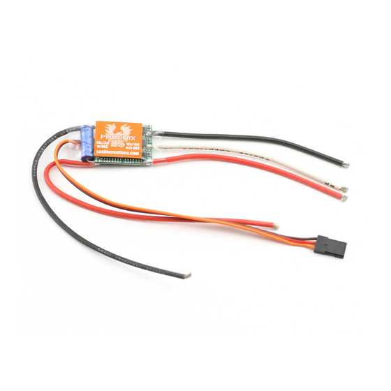
Battery
Connector
Fig 1: Motor wiring diagram
2.5
Connecting the Receiver
Older AirTronics systems require a minor change to the wiring in the receiver connector supplied with the
speed controller. Reverse the red (power) and brown (ground) wires in the connector plug so that the plug is
orange/brown/red. Use a knife blade to lift the retention tabs on the connector plug to remove the red and
brown wires. Insert the wires back into the plug and press down the retention tab.
Connect the receiver lead (the three color twisted wires with a connector on the end) to the throttle channel on
your receiver (usually channel 3). Do not connect a battery to the receiver, as the Phoenix-25™ will supply
power to the receiver and servos through the receiver connector. If you are using more than ten cells, you
must use a separate receiver battery. See the section 4.0 (under the heading BEC) for instructions on
disabling the BEC to use a separate receiver battery.
Rev 5-date 11/13/02
Castle Creations
Phoenix-25™
Motor
Phoenix-25™
Advertisement

Subscribe to Our Youtube Channel
Related Manuals for Castle Creations PHOENIX-25

Summary of Contents for Castle Creations PHOENIX-25
- Page 1 7-8 cells 9-10 cells your receiver (usually channel 3). Do not connect a battery to the receiver, as the Phoenix-25™ will supply Standard (micro) servos power to the receiver and servos through the receiver connector. If you are using more than ten cells, you High Torque servos must use a separate receiver battery.
-
Page 2: Troubleshooting
After radio connection has been reestablished, Your Phoenix-25™ is warranted for one (1) year from date of purchase to be free from manufacturing and moving the throttle to the braking position (full off) for four seconds can restart the motor. - Page 3 Phoenix-25™ has accepted your answer, it will flash the LED rapidly. After the LED starts it’s rapid flashing, Verify Normal Operation move the throttle stick to the middle position to confirm that you are ready for the Phoenix-25™ to ask the next question.
- Page 4 NOTE: Change this setting at your own risk! Damage to the controller as a result of over current is NOT covered by the manufacturer’s warranty. Only experienced modelers should use this programming feature. Current limiting describes the reaction of the Phoenix-25™ when an over-current condition is detected. There are five options:...
- Page 5 Return Tx stick to center and proceed to next option for this No – Throttle stick in off position setting PHOENIX-25™ User Guide Page 5 of 6 Rev 5-date 11/13/02 This document, Phoenix-25™ software, and Phoenix-25™ PCB layout are all Copyright 2002 by Patrick del Castillo and Castle Creations...
- Page 6 User’s Guide (section 3) to arm the unit for flight. to confirm it is ready to be armed. PHOENIX-25™ User Guide Page 6 of 6 Rev 5-date 11/13/02 This document, Phoenix-25™ software, and Phoenix-25™ PCB layout are all Copyright 2002 by Patrick del Castillo and Castle Creations...
Need help?
Do you have a question about the PHOENIX-25 and is the answer not in the manual?
Questions and answers