Table of Contents
Advertisement
Quick Links
Operator's and Maintainer's Manual
for the
Fire Control System
PN: 64000G10
WARNING
You are required to thoroughly read all instructions and product safety
information in the BOSS-Xe Operator's Manual before using this
product. FAILURE TO COMPLY WITH PROPER INSTRUCTIONS COULD RESULT
IN PROPERTY DAMAGE, INJURY AND/OR DEATH. Wilcox is not responsible
for damages resulting from improper use and/or maintenance. Customers
may obtain a copy of the Manual by contacting Wilcox Customer Service at
603-431-1331.
This manual and product contain technical data as defined in the
International Traffic in Arms Regulations ITAR 22 CRF 120.10. Export of
this material is restricted by the Arms Export Control Act 22 U.S.C. 2751
et seq. and may not be exported to foreign persons without prior written
approval from the U.S. Department of State.
21 January, 2021
64000M05
Rev. A-1
Advertisement
Table of Contents

Summary of Contents for Wilcox BOSS-Xe
- Page 1 IN PROPERTY DAMAGE, INJURY AND/OR DEATH. Wilcox is not responsible for damages resulting from improper use and/or maintenance. Customers may obtain a copy of the Manual by contacting Wilcox Customer Service at 603-431-1331. This manual and product contain technical data as defined in the International Traffic in Arms Regulations ITAR 22 CRF 120.10.
-
Page 3: Table Of Contents
S1 - Laser Radiation Output Parameters ........xiv SECTION 1 - OVERVIEW General Safety Warnings ..........1 SECTION 2 - INTRODUCTION Product Description ............3 Major Components ......4 BOSS-Xe List of Subcomponents and Features ..5 BOSS-Xe List of Major Components ..... 9... - Page 4 Operator’s and Maintainer’s Manual for the TABLE OF CONTENTS (CONT'D) Para. No. Title Page ..........26 BOSS-Xe Operating the 3.3.1 Performing Daytime Engagement ............27 BOSS-Xe with the 3.3.2 Performing Nighttime Engagement ............28 BOSS-Xe with the BOSS-Xe 3.3.3 Performing Engagements with the Powered Off ..............
- Page 5 Operator’s and Maintainer’s Manual for the TABLE OF TABLES Table No. Title Page Spare Parts List ............44 System Laser Safety Parameters .... xiv BOSS-Xe S1-1 Button Operations (by Mode) ........12 2.5-1 Mode Operations Tree ..........13 2.5-2 Reticle Shape Selection Switch Position Options ... 13 2.5-3...
- Page 6 Operator’s and Maintainer’s Manual for the TABLE OF ILLUSTRATIONS (CONT’D) Fig. No. Title Page 2.3-3 Subcomponent Identification (3 of 4) ............7 BOSS-Xe 2.3-4 Subcomponent Identification ................ 8 BOSS-Xe 2.3-5 Cleaning Kit Identification (4 of 4) ............8 BOSS-Xe Control Pad Functionality ........... 12 2.5-1...
-
Page 7: Preface
Department, Wilcox Industries, Corp., One Wilcox Way, Newington, NH 03801. To submit feedback by e-mail, visit www.wilcoxind.com © 2020-2021 Wilcox Industries Corp. All rights reserved. Printed in USA. US Patents. 9,752,853, 10,086,527, 10,557,687, 10,581,214, and 10,175,029. Wilcox Additional US and foreign patents pending. - Page 8 Operator’s and Maintainer’s Manual for the OPERATOR’S MANUAL TO SOFTWARE VERSION CROSS-REFERENCE BOSS-Xe When utilizing any version of the software, it is critical to reference the correct version of the Operator’s Manual for the software you are using. The following table provides a cross-reference for tracking Operator’s Manual...
-
Page 9: Safety Summary
Operator’s and Maintainer’s Manual for the SAFETY SUMMARY WARNING and CAUTION statements have been strategically placed throughout the text to indicate operating or maintenance procedures, practices, or conditions considered essential to the protection of personnel (WARNING) or equipment and property (CAUTION). NOTES emphasize necessary and important data. - Page 10 WARNING Laser Safety The BOSS-Xe features a Class 3B laser product which emits visible and infrared laser radiation from the front end of the device. Both visible and infrared laser light can be dangerous if misused. Laser light reflected or refracted off mirrored surfaces may be equally harmful.
- Page 11 Industries at 603-431-1331 and do not use this product. Do not fire the weapon if the BOSS-Xe displays a left or right cant indicator, as this is an indication that the BOSS-Xe is canted left or right. Firing the weapon when the BOSS-Xe is severely canted can cause unintended damage to surrounding targets and may result in injury or death.
- Page 12 Failure to maintain the O-Ring may affect product performance. Maintenance Safety ALWAYS ensure that primary (CR123) battery is removed prior to mounting the BOSS-Xe to, or dismounting it from the primary weapon or when performing service. WARNING Battery Safety ...
- Page 13 Always ensure that the primary battery is removed prior to mounting the BOSS-Xe to, or dismounting it from the primary weapon or when performing service. The BOSS-Xe features a cant indicator that faces the operator when in a firing position.
- Page 14 The operator should perform regular maintenance as outlined in this manual. Any procedures not specifically outlined in this manual shall be performed only by a Wilcox certified maintenance technician. Performance of procedures outside of those specified in this manual will invalidate the product warranty.
-
Page 15: S1 Laser Radiation Output Parameters
Operator’s and Maintainer’s Manual for the Laser Radiation Output Parameters BOSS-Xe System Table S1-1 Laser Safety Parameters BOSS Xe Laser Parameters NIR Aim NIR Illum Vis Aim High Low Class Wavelength [nm] Laser Power <0.7 <0.7 <0.7 [mW] NSHD [m]... -
Page 16: Section 1 - Overview
Operator’s and Maintainer’s Manual for the SECTION 1 OVERVIEW GENERAL SAFETY WARNINGS BOSS-Xe should not be used by anyone unfamiliar with its operation. This manual contains specific operating and maintenance instructions which the operator should become familiar with before actual field usage. -
Page 17: Boss-Xe
It is the responsibility of the operator to read and thoroughly understand the handling and operating BOSS-Xe procedures for both the and the primary weapon to which it is installed. -
Page 18: Section 2 - Introduction
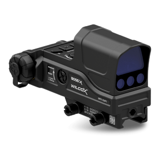
Operator’s and Maintainer’s Manual for the SECTION 2 INTRODUCTION 2.1 PRODUCT DESCRIPTION BOSS-Xe The Wilcox Fire Control System provides repeatable accuracy that cannot be found with any other fire control system. It features a fully integrated Reflex Sight, Visible Red Laser, IR Laser, IR Laser Illuminator and Fixed IR LED Room Illuminator. -
Page 19: List Of Boss-Xe Major Components
Operator’s and Maintainer’s Manual for the BOSS-Xe 2.2 LIST OF MAJOR COMPONENTS BOSS-Xe Carrying Pouch Remote Trigger BOSS-Xe Operator’s and Maintainer’s Manual BOSS-Xe Quick Reference Boresight Chart Figure 2.2–1 Major Component Identification 64000M05 Rev. A-1... -
Page 20: List Of Boss-Xe Subcomponents And Features
Operator’s and Maintainer’s Manual for the BOSS-Xe 2.3 LIST OF SUBCOMPONENTS AND FEATURES ITEM DESCRIPTION U-1. Optic Sight U-2. Main Battery Compartment U-3. Windage Adjustment Knob U-4. Thumb Screws (2) BOSS-Xe Figure 2.3–1 Subcomponent Identification - (1 of 4) 64000M05... - Page 21 U-14. IR Illuminating Laser Port U-15. IR LED Room Illuminator U-16. Lock-Out Screw U-17. Lock-Out Screw Retention Hole U-15 U-18. Laser Warning Label U-10 U-11 U-16 U-17 U-18 BOSS-Xe Figure 2.3–2 Subcomponent Identification - (2 of 4) 64000M05 Rev. A-1...
- Page 22 Iron Sights U-20. LED Indicator U-21. Dot Sight U-22. Cant Indicators (Not Shown) U-23. Processor Clock Battery Compartment U-24. Remote Interface Port U-21 U-22 U-19 U-20 U-24 U-23 BOSS-Xe Figure 2.3–3 Subcomponent Identification - (3 of 4) 64000M05 Rev. A-1...
- Page 23 Operator’s and Maintainer’s Manual for the ITEM DESCRIPTION CK-1. Cleaning Brush CK-2. Cleaning Cloth AK-1. Lens Cover AK-2. Battery Cap Assembly AK-2 AK-1 BOSS-Xe Figure 2.3–4 Subcomponent Identification - (4 of 4) CK-2 CK-1 BOSS-Xe Figure 2.3–5 Cleaning Kit Identification - 64000M05 Rev. A-1...
-
Page 24: Boss-Xe
Operator’s and Maintainer’s Manual for the BOSS-Xe 2.4 DESCRIPTION OF MAJOR COMPONENTS BOSS-Xe BOSS-Xe . The features a fully integrated optic Sight, Visible Red Laser, IR Laser, IR Laser Illuminator and Fixed IR LED Room Illuminator. It allows the user to interchangeably utilize supersonic and subsonic ammunition by the flip of a single... -
Page 25: Description Of Boss-Xe Sub-Components
Operator’s and Maintainer’s Manual for the BOSS-Xe 2.5 DESCRIPTION OF SUB-COMPONENTS U-1. Optic Sight. The integrated Optic Sight is a red dot sight that provides the sighting and targeting capability for the BOSS-Xe . It features an IR Aiming Laser, IR Illuminator Laser and Visible Aiming Laser that provide invisible targeting, day and night. - Page 26 Trajectory Switch is in the “A2” position. It aids boresighting or Zeroing the BOSS-Xe to the weapon and maintains its setting until reset by the operator. All Lasers and the Red Dot Sight move together when adjusting elevation.
-
Page 27: Button Operations (By Mode)
** Active lasers will time out after 5 minutes of continuous use. Activate Activate Optional Activate Laser Flashlight Remote Trigger BOSS-Xe Control Pad Figure 2.5–1 Control Pad Functionality 64000M05 Rev. A-1... -
Page 28: Reticle Shape Selection Switch Position Options
Operator’s and Maintainer’s Manual for the Table 2.5-2. Mode Options Tree KNOB MODE / FUNCTION POSITION DESCRIPTION Dual IR Aiming Laser and Long Range IR Illuminator- IR DH High Power (Can Be Locked Out with Lockout Screw) IR Aiming Laser - High Power IR AH (Can Be Locked Out with Lockout Screw) Dual IR Aiming Laser and IR LED Room Illuminator... - Page 29 Knob allows the operator to adjust as what distance the laser intersects the bullets trajectory, when in the A1 position. U-11. A1 / A2 Switch. The A1 / A2 Switch mechanically changes BOSS-Xe the trajectory of the Optic Sight, including all co-aligned lasers and the red dot, between two pre-set points of aim (e.g.,...
- Page 30 Operator’s and Maintainer’s Manual for the BOSS-Xe U-13. Visible Aiming Laser Port. The Optic Sight features a 640nm Visible Red Aiming Laser that is used as a boresighting aid. Refer to Sections S1, “Laser Radiation Output Parameters” and 2.6 “Technical Data” for laser specifications.
- Page 31 On Red Both Low Battery Blink Red and Green and Any Laser Active BOSS-Xe U-21. Red Dot Sight. The features a Red Dot Sight with an expanded reticle design which simplifies finding the reticle and can be used for scaling objects to approximate target distances.
- Page 32 Operator’s and Maintainer’s Manual for the U-22. Cant Indicators. Cant indication is provided to warn the BOSS-Xe operator that the is canted left or right and should be brought back to level to avoid hitting off-target. When the weapon is canted, cant indication is provided on the reticle by blinking one of the side arcs.
- Page 33 CK-2. Cleaning Cloth. A cleaning cloth is provided for removing any remaining residue from the lenses after they have been blown clean of dirt and dust. For cleaning instructions, refer to BOSS-Xe” Section 4.1, “Care of the AK-1. Lens Cover. One Lens Cover is included with the...
-
Page 34: 2.6 Technical Data
Operator’s and Maintainer’s Manual for the 2.6 TECHNICAL DATA BOSS-Xe Table 2.6-1. Technical Data ADDITIONAL SPECIFICATIONS Lasers powered with One (1) CR123 Battery. Power Source Additionally, one (1) CR1220 coin cell maintains the processor clock when the system is powered off. The estimated life of this battery is 3-5 years. -
Page 35: Section 3 - Operation
Ensure that the weapon is CLEAR and on SAFE before installing the BOSS-Xe on a weapon, in accordance with the weapon’s Operator’s Manual, and that the BOSS-Xe is powered off, lens cap on prior to installation. Failure to so can result in property damage, injury, and/or death. - Page 36 Operator’s and Maintainer’s Manual for the BOSS-Xe To Mount the to the Primary Weapon: LOOSEN BOTH RAIL GRABBERS BY TURNING THE THUMB NUTS CCW. POSITION THE MOUNT ON THE RAIL, ENSURING THAT THE RAIL GRABBERS ENGAGE. SECURE THE THUMB NUTS BY TURNING CW AND TORQUING TO 30 IN/LBS.
-
Page 37: Boresight Procedure (Establishing Theoretical Zero With A Laser Boresight Kit)
To align the lasers to target at greater distances, a Zeroing procedure consisting of live fire is used. WARNING When mounting the BOSS-Xe to a weapon, or to a new rail position, it is necessary to properly boresight the BOSS-Xe to the weapon to ensure aiming accuracy. - Page 38 Operator’s and Maintainer’s Manual for the NOTE It is recommended that the Visible Laser be used for boresighting the BOSS-Xe to the target. Laser Boresight Procedure: Boresighting the First (Shorter) Trajectory (A1) with a Laser Boresight Kit: Step 1.) Ensure that the weapon is clear and SAFE.
- Page 39 Operator’s and Maintainer’s Manual for the BOSS-Xe Step10.) Adjust the to the corresponding labeled position on the chart by rotating the Windage and Elevation Control Knobs. Use the cant indicators BOSS-Xe while boresighting to ensure that the level. Zeroing the Second (Longer Range or Greater Drop) Trajectory (A2) with Live Fire: Step 11.) Ensure that the weapon is clear and SAFE.
-
Page 40: Boss-Xe (64000G10) Boresight Chart
Operator’s and Maintainer’s Manual for the BOSS-Xe Figure 3.2-1 (64000G10) Boresight Chart 64000M05 Rev. A-1... -
Page 41: Operating The Boss-Xe
fire. WARNING Do not fire the weapon if the BOSS-Xe displays a left or right cant indicator. Firing the weapon when the BOSS-Xe is canted can cause unintended damage to surrounding targets and may result in injury or death. - Page 42 Operator’s and Maintainer’s Manual for the BOSS-Xe 3.3.1 Performing Daytime Engagement with the BOSS-Xe To Perform Daytime Engagement with the Step 1.) Remove the Lens Cover. Step 2.) Rotate the Mode Selection Knob to a daytime operational position (refer to Table 2.5-2, “Mode Options Tree”).
-
Page 43: Performing Nighttime Engagement With The Boss-Xe
Step 3.) Press the Center Button to activate the selected laser(s). WARNING When adjusting BOSS-Xe trajectory, use caution to ensure that lasers are not fired in an unsafe manner. Step 4.) Verify that the weapon is level to the horizon (not BOSS-Xe canted) by checking for cant indication. - Page 44 Operator’s and Maintainer’s Manual for the Table 3.5-1 IR Aiming Laser Cant Indication CAUSE CANT INDICATION Unit Canted Left - Do not Fire Slow Blink Rate Fast Blink Rate Unit Canted Right - Do not Fire Step 5.) Fire the weapon. 64000M05 Rev.
-
Page 45: Performing Engagements With The Boss-Xe Powered Off
Operator’s and Maintainer’s Manual for the BOSS-Xe 3.3.3 Performing Engagements with the Powered Off BOSS-Xe To Perform Engagements with the Powered Off: BOSS-Xe can still be used to accurately engage targets without being powered on through the use of the iron sights. -
Page 46: 3.3.4 Activating The Panic Alert
Operator’s and Maintainer’s Manual for the 3.3.4 Activating the Panic Alert To Activate the Panic Alert: BOSS-Xe A panic alert functionality is available for the System when Bluetooth is turned on and the system is BOSS-Xe connected to a device supporting the protocols. -
Page 47: Section 4 - Maintenance
CARE OF THE WARNING ALWAYS ensure that primary (CR123) battery is removed prior to mounting the BOSS-Xe to, or dismounting it from the primary weapon or when performing service. NOTE Do not use harsh abrasives or chemicals such as acetone to clean the BOSS-Xe. - Page 48 Operator’s and Maintainer’s Manual for the The operator should perform regular maintenance as outlined in this manual. Any procedures not specifically outlined in this manual shall be performed only by a Wilcox certified maintenance technician. Performance procedures outside of those specified in this manual will invalidate the product warranty.
-
Page 49: Battery Replacement
The LED Indicator displays a solid red when the CR123 battery becomes low, and alternates red and green when the CR123 battery is low and any laser is active. When this BOSS-Xe occurs, performance of the will be degraded and the battery should be replaced immediately. - Page 50 Operator’s and Maintainer’s Manual for the BOSS-Xe To Replace the Battery in the Remove CR123 battery then inspect battery compartment and cover o-ring for residue or moisture. Replace O-Ring if necessary. Install a fresh battery, ensuring that the “+” side is inserted first.
- Page 51 Operator’s and Maintainer’s Manual for the BOSS-Xe To Replace the Processor Clock Battery in the Clock Battery Main Battery Remove the main battery, then inspect battery compartment and cover o-ring for residue or moisture. Replace O-Ring if necessary. ...
-
Page 52: Inspecting And Replacing O-Rings
For this reason, it is strongly advised that they be replaced whenever they are removed, to ensure proper sealing of the compartment. O-Ring replacements are available through Wilcox and should be purchased in advance of need to ensure continued service. Step 1.) Gently brush any debris away from the o-rings with the cleaning brush provided. -
Page 53: Inspecting And Replacing O-Rings
Gently lubricate the O-Ring on both sides, with the thumb and index finger, using Silicone Grease. Using the pick tool, gently replace the lubricated O-Ring, using caution not to overstretch or damage. BOSS-XE BOSS-XE BATTERY CAP PROCESSOR O-RING ( 1 ) -
Page 54: Storage
BOSS-Xe Reattach the laser cover to the to prevent dust BOSS-Xe and dirt entry. Remove battery from the retain. Do not store the BOSS-Xe with the primary (CR123) battery installed. SHIPPING BOSS-Xe, Prior to shipping the follow cleaning and storage instructions as described in Sections 4.1 and 4.4. -
Page 55: Appendix A - Warranty Statement
APPENDIX A WARRANTY STATEMENT STANDARD LIMITED WARRANTY Wilcox Industries Corp. (“WX”) offers a limited warranty ("Limited Warranty") that its products will be free from defects in material and workmanship under proper usage for one (1) year from the date of original shipment by WX if purchased through an authorized sale. - Page 56 Operator’s and Maintainer’s Manual for the WX MAKES NO OTHER WARRANTIES, EXPRESS OR IMPLIED. WX SPECIFICALLY DISCLAIMS ALL OTHER WARRANTIES, EXPRESS OR IMPLIED, INCLUDING BUT NOT LIMITED TO, THE WARRANTIES OF MERCHANTABILITY AND/OR FITNESS FOR A PARTICULAR PURPOSE. This Limited Warranty is purchaser’s sole and exclusive remedy for warranty coverage, WX conduct, or for any other claim or cause of action against WX.
-
Page 57: Warranty Claim And Service Information
(SC) prior to return shipment. After an RMA/SC number is provided, WX will accept a package at the address below, clearly marked with the number assigned as follows: Wilcox Industries Corp. RMA # ____________ 25 Piscataqua Drive Newington, NH 03801... -
Page 58: Appendix B - Abbreviations
Operator’s and Maintainer’s Manual for the APPENDIX B ABBREVIATIONS ABBREVIATIONS Counter-Clockwise CU IN Cubic Inches Clockwise FWHM Full Width of Half Maximum In/lb Inch Pound ITAR International Trafficking in Arms Regulations Pound Millimeter mrad Milliradian Nanometer Night Vision Device Night Vision Goggle Ounce 64000M05 Rev. -
Page 59: Spare Parts List
Operator’s and Maintainer’s Manual for the APPENDIX C SPARE PARTS SPARE PARTS LIST To order replacement parts, contact the Wilcox marketing department at 603-431-1331. Please specify your product color when ordering. REPAIR PART NO DESCRIPTION REFERENCE TYPE C.1.1 65301P14 STRAP ‐ CR123 BATTERY TUBE ... - Page 60 Operator’s and Maintainer’s Manual for the NOTES: 64000M05 Rev. A-1...
- Page 62 Manufactured by: Wilcox Industries, Corp. One Wilcox Way Newington, NH 03801-7816 Phone: 888-8WILCOX 603–431–1331 Fax: 603–431–1221 WWW.WILCOXIND.COM For troubleshooting service questions, contact Wilcox between 8am and 5pm EST.
Need help?
Do you have a question about the BOSS-Xe and is the answer not in the manual?
Questions and answers