Table of Contents
Advertisement
Quick Links
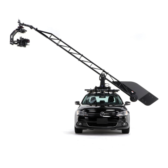
ULTRA Troubleshooting Guide v2.0
July 2020
This guide helps users diagnose and repair issues in the field.
It should be used in conjunction with the ULTRA Operation Manual.
If a quick fix is available, one is prescribed. If a quick fix is not possible, we give a service
procedure for repair using the spare parts in the Deadlock Service Kit (available for purchase
online). Without a Deadlock Service Kit, spare parts can be purchased individually or the
affected modules can be returned to MotoCrane for repair.
Via MotoCrane Academy, Certified Technicians and Operators are trained on how to perform
these more common service procedures. Find more information at
www.motocrane.com/academy
.
1
Advertisement
Table of Contents

Related Manuals for MotoCrane Ultra

Summary of Contents for MotoCrane Ultra
- Page 1 Without a Deadlock Service Kit, spare parts can be purchased individually or the affected modules can be returned to MotoCrane for repair. Via MotoCrane Academy, Certified Technicians and Operators are trained on how to perform these more common service procedures. Find more information at...
-
Page 2: Table Of Contents
Contents Understanding System Feedback COM and Power LEDs GUI Warning and Error Messages Diagnosing Common Issues “I have anodizing/finish problems” “Grease is Leaking from the Base” “Swing is not working” “Lift is not working” “The system is not turning on” Appendix 1: Diagnosis Procedures External Deactivation of Lift Drive Brake “Remove PSU Top”... -
Page 3: Understanding System Feedback
Understanding System Feedback ULTRA provides system feedback using two primary methods: LEDs and GUI Messages. COM and Power LEDs The Base Driver Unit, Base Pedestal, PSU, and Turret all contain LEDs to help quickly identify problems with electrical connections. ... -
Page 4: Gui Warning And Error Messages
GUI Warning and Error Messages ULTRA has multiple internal sensors and an error reporting system built into the GUI. If an active error or warning is present, the respective red or yellow icon will be displayed. A yellow icon indicates a warning, and the controller will beep once to alert ... -
Page 5: Diagnosing Common Issues
● Cracking Anodizing around boom fasteners. ○ Cause : Washers are needed to minimize surface abrasion. ○ Operation Manual : See ULTRA Boom + Isolator Setup on p. 21 to ensure customers are using washers appropriately. ○ Repair Procedure : N/A ○... -
Page 6: Swing Is Not Working
2) Swing joystick failure STATUS LED on? Solution: Replace joystick or contact MotoCrane Support (green) ISSUE 3) Controller Board failure Solution: Replace Controller board or contact MotoCrane Support Is Turret MAIN Base Driver Circuit POWER STATUS ISSUE 4) PSU/Cable failure Board has failed - LED on? (green) Solution: Replace PSU, Cables or contact MotoCrane Support... -
Page 7: Lift Is Not Working
Release E-Stop Solution: Replace joystick or contact MotoCrane Support Is Base Pedestal ISSUE 3) Controller Board failure MAIN POWER Solution: Replace Controller board or contact MotoCrane Support STATUS LED on? (green) ISSUE 4) PSU/Cable failure Solution: Replace PSU, Cables or contact MotoCrane Support Is BDU MAIN ISSUE... -
Page 8: The System Is Not Turning On
Base or ISSUE 3) Lift Encoder Board failure PSU Main Power Input Voltage STATUS LED is Turret Solution: Replace Lift Encoder Board or contact MotoCrane Disconnect Main Meter On? probably burned out Support Power Output Cable from PSU ISSUE... -
Page 9: Appendix 1: Diagnosis Procedures
Appendix 1: Diagnosis Procedures External Deactivation of Lift Drive Brake In a rare situation, it is possible that the lift motor driver electronics could fail due to extreme overuse, disregard for system warnings, faulty cables, improper system power supply, among others. Because the nature of the lift drive brake is ‘fail-safe’, this means that when the system is unpowered (more specifically, the lift motor driver electronics ... -
Page 10: Remove Psu Top
“Remove PSU Top” “Remove 24V Power Fuse” “Check Power Fuse for Continuity” NO Continuity Y ES Continuity ... -
Page 11: Unplug Can-Trvl, Check Pins 3 And 4 For Continuity
“Unplug CAN-TRVL, Check Pins 3 and 4 for Continuity” “Check continuity across Pins H and J on the BDU Main Power Input Socket” N O Continuity Y ES Continuity “Open Base Pedestal Plate, Remove CAN IN Connector” ... -
Page 12: Remove Lift Encoder Cover, Unplug Can In From Lift Encoder Board
“Remove Lift Encoder Cover, Unplug CAN IN from Lift Encoder Board” “Check continuity between pins H and J on the LDU Main Power Input Socket” N O Continuity Y ES Continuity “Emergency Bypass Procedure” (for PSU Circuit Board failure) NOTE:... - Page 13 removing the capacitors, the fuse will need to be replaced or bypassed with a conductor, since the fuse fails in an open-circuit configuration. Please refer to the following images and descriptions for information about removing these capacitors and bridging the fuse connection. FUSE BYPASS A common multi-strand wire can be used to bypass (bridge) the fuse.
- Page 14 REMOVE C10 and C11 CAPACITORS While it is preferable to use a hot air/soldering station, a small jeweler’s/precision screwdriver can be used to “pop” or “pry” the damaged C10 and C11 capacitors off of the PSU circuit, making the circuit functional again.
-
Page 15: Appendix 2: Error Codes Lookup Table
Turret internal wiring or moves in high ambient electronics. Service on the Turret by temperatures MotoCrane is required to resolve this issue. The unit can still be used with caution, but should be serviced at the earliest convenience. ... - Page 16 ● Avoid heavy use of lift to the Turret electronics. Service on the moves in high ambient Turret by MotoCrane is required to temperatures resolve this issue. The unit can still be used with caution, but should be serviced ...
- Page 17 ● Avoid extreme Turret electronics. Service on the Turret movements of lift axis by MotoCrane is required to resolve this and make sure payload issue. The unit can still be used with and counterweight are ...
- Page 18 Imbalance - are properly balanced, is available (within the Settings+ page of Front Heavy in accordance with the the GUI) to enable ULTRA to auto-detect Operation Manual Payload/CW imbalances. The system can instructions generally detect situations where the Payload is more than +/- 5 lbs ...
- Page 19 Heartbeat reset electronics are not detected in the ● Double check all cable Timeout system. This error will be triggered if the connections Turret is not connected to the system, or if the cable between the Base Pedestal and the Turret has failed. COM LEDs on the Turret may also help to isolate the ...
- Page 20 ● Avoid heavy use of to the Base internal wiring or electronics. swing moves in high Service on the Base by MotoCrane is ambient temperatures required to resolve this issue. The unit can still be used with caution, but should ...
- Page 21 ● Avoid extreme the Base electronics. Service on the Base movements of swing by MotoCrane is required to resolve this axis under high load issue. The unit can still be used with caution, but should be serviced at the ...
- Page 22 can still be used with caution, but should be serviced at the earliest convenience. ● Power cycle system to 069 Swing Motor This error indicates that the swing driver Command reset board is not receiving commands from ● Double check all cable Timeout ...
- Page 23 ● Use caution and 082 Swing Encoder This warning indicates that valid data is Data Invalid contact MotoCrane not being received from the swing Support encoder. Limits are not allowed while this ● Try power cycling the condition is active, to ensure that bad ...
- Page 24 ● Use caution and 102 Lift Encoder This warning indicates that valid data is Data Invalid contact MotoCrane not being received from the lift encoder. Support Limits are not allowed while this ● Try power cycling the condition is active, to ensure that bad ...
- Page 25 Warning voltage higher than this can potentially cause system damage. ● Ensure correct voltage 122 System This warning will be triggered if the Under-Voltage of power source system voltage is below 46V. Applying Warning voltage lower than this can potentially disable the system and prevent normal ...
- Page 26 PSU or Controller THE PSU ‘COM’ PORT, electronics. Service on both of these units NOT ‘AUX’ by MotoCrane is required to resolve this ● Otherwise, contact issue. The unit can still be used with MotoCrane Support ...
- Page 27 If your system is experiencing general wear and tear, we can advise what options exist to get your system back to 100%. This includes sub-assembly upgrades, component replacement, or sending your unit back to MotoCrane Headquarters for a tune up. ...
- Page 28 ...
-
Page 29: Revision History
This content is subject to change. Download the latest version from www.motocrane.com/support If you have any questions about this document, please contact MotoCrane, LLC by sending a message to c ontact@motocrane.com . ©2019 MotoCrane, LLC. All rights reserved.
Need help?
Do you have a question about the Ultra and is the answer not in the manual?
Questions and answers