Advertisement
Table of Contents
- 1 Table of Contents
- 2 Compatibility
- 3 What's in the Box
- 4 Before You Start
- 5 Installing Your Thermostat
- 6 Wiring Diagram
- 7 User Interface
- 8 Heating Modes
- 9 Set the Time and Date
- 10 Heating Schedule
- 11 Energy Saving Features
- 12 Advanced Settings
- 13 Factory Reset & Key Lock
- 14 Technical Data
- 15 Troubleshooting Guide
- Download this manual
Advertisement
Table of Contents

Related Manuals for ThermoSphere SCP-W


Summary of Contents for ThermoSphere SCP-W
- Page 1 INSTRUCTION GUIDE SCP-W SCP-B CONTROL | TOUCH SINGLE PROGRAMMABLE Live well...
-
Page 2: Table Of Contents
Contents Compatibility .............. What's in the box? ............. Before you start ............Installing your thermostat ........... Wiring diagram ............User interface ............. Heating modes ............Set the time and date ..........Heating schedule ............Energy saving features ..........Advanced settings ............Factory reset &... -
Page 3: Compatibility
Sensor probes This thermostat is compatible with ThermoSphere NTC 10kΩ @ 25°C floor sensor probes. Heating systems This thermostat is compatible with all ThermoSphere electric underfloor heating systems Replacing an existing thermostat? Contact the manufacturer's technical department and ask for the rating of the floor sensor at 25°C. -
Page 4: What's In The Box
What’s in the box? Check you've got everything: • Programmable thermostat • Floor sensor probe (3m) • Floor sensor conduit (2m) • Fixing screws • Installation guide and warranty information • Portrait mounting plate You will also need: • Electrical screwdriver •... -
Page 5: Before You Start
Before you start Your thermostat should be: • Installed at least 1.2m from the floor • On an internal wall • Outside any wet zones (IP30) • Installed on an RCD protected circuit • Away from any hot or cold influences •... -
Page 6: Installing Your Thermostat
Installing your thermostat 1. Switch off mains power You will be installing your thermostat as part of a high voltage mains electrical CAUTION circuit. To ensure your safety and to High Voltage protect the thermostat, switch off the Cables mains power and remove fuse from the spur before you start the installation. - Page 7 Installing your thermostat 2. Installation location At this stage it its likely that an RCD protected electric underfloor heating system has been installed and a back box is already in place. The underfloor heating cold tail should be pulled up through the back box, and the sensor probe installed (in the conduit provided) within the wall cavity or pre chased channel in a solid wall.
- Page 8 Installing your thermostat 3. Maximum distances Your thermostat can be installed up to 50m away from the underfloor heating system it is controlling, provided that the floor sensor is used to control the temperature. Underfloor heating cold tails and floor sensor probes can be extended up to 50m.
- Page 9 Installing your thermostat 4. Un-clipping the mounting plate Lay thermostat screen side Press the white clip down Push the mounting plate down on a flat surface with a flat screwdriver towards you Use your phone camera to watch the video Release the mounting plate Carefully un-clip the white form the clips...
-
Page 10: Wiring Diagram
Installing your thermostat 5. Wiring diagram Connect the Thermostat to the underfloor heating (UFH) cold tail, power supply and floor temperature sensor. The floor temperature sensor is not polarity sensitive. 230/240V AC Supply Live 230/240V AC Supply Neutral UFH Neutral (Load N) UFH Live (Load L) Earth (Ground) Sensor connections... - Page 11 Installing your thermostat 6. Fix mounting plate in position Use a cross-head screwdriver to fix the mounting plate to the back box in the wall. Now you can connect the white ribbon cable to the fascia.
- Page 12 Installing your thermostat 7. Fix thermostat fascia in place Locate the thermostat onto the mounting plate and push down to clip in place.
- Page 13 Switching on for the first time Do not switch your underfloor heating on unless the entire heating cable, cold tail joint and end termination are fully encased in tile adhesive. Wait for 7 - 10 Days It is important that all adhesives and before you grouting are dry and fully cured before you switch on...
-
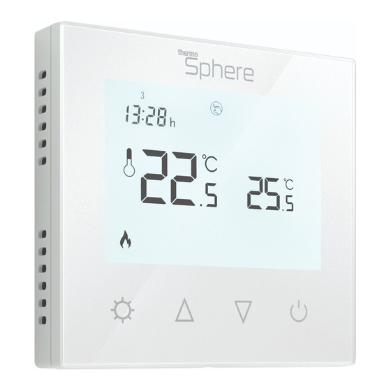
Page 14: User Interface
User interface 1. Day indicators 6. Mode button 11. Set temperature 2. Time 7. Up arrow 12. Manual mode icon 3. Measured temperature 8. Down arrow 13. Schedule mode icon 4. Heating on icon 9. Power button 5. Lock icon 10. -
Page 15: Heating Modes
Heating modes When your thermostat is on you can tap to switch between Manual and Schedule heating modes. Manual mode Your thermostat will simply maintain the temperature you set manually until you ask it to do something else! Schedule mode Your thermostat will follow a heating schedule that you can set up. - Page 16 Temperature override Temperature override When the thermostat is in Schedule mode, running your heating timer settings, it is possible to manually override the temperature without adjusting the schedule or switching to manual mode. You can adjust the temperature with the arrows.
-
Page 17: Set The Time And Date
Setup Setting the day and time Switch the unit off by pressing Press and hold for 7 seconds until the time begins to flash. to select the correct minute. Press to switch to hours and use select the correct hour. Press again to edit the day and use select the correct day. -
Page 18: Heating Schedule
Set up your heating schedule 1. Turn the thermostat on by pressing 1. Press to switch to mode before you start. 2. Press to switch the unit off. 3. Press and hold for 7 seconds to edit your schedule. If you have already set the clock press x3 to skip it. - Page 19 Set up your heating schedule 8. Press to save. Now use to select the desired Comfort (or “On”) temperature between 20 - 28°C. 9. Press to advance to event 4 and use to select the desired time to switch to a lower temperature. Event 4 10.
-
Page 20: Energy Saving Features
Energy saving features You can activate and adjust these features in the advanced settings menu. See page 21 - 23. Adaptive Start With the Adaptive Start feature enabled your thermostat will measure how long it takes for your individual floor to heat up and ensure the target temperature is achieved at the set time. -
Page 21: Advanced Settings
Advanced settings Adjusting the advanced settings To access the settings, switch the unit off by pressing Press and hold together for 7 seconds. Press to cycle between settings. to adjust the settings. Switch the unit on by pressing to save your settings. - Page 22 Advanced settings MENU DESCRIPTION RANGE DEFAULT Temperature calibration -8°C ~ 8°C 0°C Maximum set point 5°C ~ 80°C 35°C Minimum set point 5°C ~ 80°C 5°C IN (Ambient), OUT (Floor), Sensor mode ALL (Ambient with floor limit) Frost protection 5°C ~ 15°C or Off 5°C Floor temperature display (ALL sensor mode only)
- Page 23 MENU DESCRIPTION RANGE DEFAULT Factory reset Re (yes) Backlight timer 10secs - 300secs (5mins) Backlight brightness level 1 (min), 2, 3, 4 (max) Adaptive Start 1 (On), 0 (Off) Open Window Detection (OWD) 1 (On), 0 (Off) OWD Off Time 2 - 30 minutes 15 mins OWD Temperature Drop Limit...
-
Page 24: Factory Reset & Key Lock
Factory reset & key lock Locking the keys To lock the keys press and hold together for 7 seconds. icon will appear when the keys are locked. None of the keys will function. To unlock the keys press and hold together for 7 seconds. -
Page 25: Technical Data
Technical data Supply voltage 230V/240V 50/60Hz Maximum load Backup storage EEPROM (approx. 1 year backup) Temperature range 5 ~ 80°C (0.5°C increments) Accuracy ±0.5°C Sensor rating NTC 10kΩ @ 25°C Consumption Warranty 3 years IP rating IP30 Width 85mm Height 85mm Depth 46mm (31mm in wall) -
Page 26: Troubleshooting Guide
8 to 12KΩ then it is likely to be a sensor probe from a different manufacturer and will need to be replaced with a ThermoSphere NTC10K sensor probe. Sometimes more than one floor sensor is connected to the thermostat by mistake. This results in a high resistance... - Page 27 Need a hand? Call us on 0800 019 5899 Problem Possible causes Things to try Isolate power and check that a compatible NTC10K sensor probe is connected to terminals 6 & 7. “Er” error No floor sensor installed message If no sensor is installed you will need to have one installed or run the system on air/ambient temperature only* If there is a sensor connected then it may be...
- Page 28 Thermogroup Ltd T/A ThermoSphere Pattenden Lane Marden TN12 9QJ 0800 019 5899 hello@thermosphere.com Live well... thermosphere.com...
Need help?
Do you have a question about the SCP-W and is the answer not in the manual?
Questions and answers
what does the icon in event 3 and event 4 mean, ie the house with the cross in it .
The house with the cross icon in event 3 and event 4 for the ThermoSphere SCP-W represents the "Out Eco" (or "Off") temperature mode. This mode sets the thermostat to a lower temperature range (16 - 20°C) when the home is unoccupied or when reduced heating is needed to save energy.
This answer is automatically generated