Table of Contents
Advertisement
Quick Links
KEEP FOR FUTURE REFERENCE
INSTRUCTIONS
International Version
P.O. Box 368 – 908 West Main
Laurel, MT USA 59044
MODEL NUMBER: __________
phone 800-548-7341
phone 406-628-8231
SERIAL NUMBER: __________
fax 406-628-8354
CLADDING LIFTER
DC-VOLTAGE
WITH DUAL VACUUM SYSTEM
AND VIFS625 PAD INSERTS
READ ALL INSTRUCTIONS AND WARNINGS
BEFORE OPERATING THIS LIFTER
DESIGNED FOR THE MATERIALS HANDLING PROFESSIONAL
Advertisement
Table of Contents

Related Manuals for WOOD'S POWR-GRIP MTCL6FS625DC


Summary of Contents for WOOD'S POWR-GRIP MTCL6FS625DC
- Page 1 KEEP FOR FUTURE REFERENCE INSTRUCTIONS International Version P.O. Box 368 – 908 West Main Laurel, MT USA 59044 MODEL NUMBER: __________ phone 800-548-7341 phone 406-628-8231 SERIAL NUMBER: __________ fax 406-628-8354 CLADDING LIFTER DC-VOLTAGE WITH DUAL VACUUM SYSTEM AND VIFS625 PAD INSERTS READ ALL INSTRUCTIONS AND WARNINGS BEFORE OPERATING THIS LIFTER DESIGNED FOR THE MATERIALS HANDLING PROFESSIONAL...
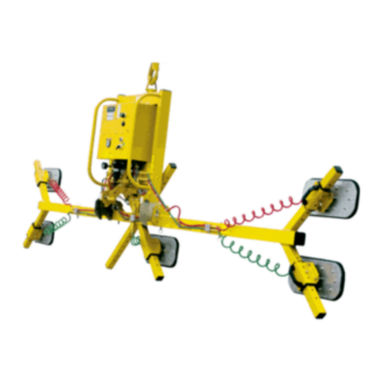
- Page 2 SPECIFICATIONS Model Number: MTCL6FS625DC Description: Designed for use with a crane or other hoisting equipment, the MTCL6FS625DC lifter employs vacuum to hold a load for lifting, and it provides manual 90° tilt movements for load manipulation. Power Source: 12 volts DC, 26 amps...
- Page 3 Wood’s Powr-Grip cannot be responsible for the safety of a lifter that has been modified by the customer. For consultation, contact Wood's Powr-Grip. Always ensure that pad seals are kept clean and dry.
-
Page 4: Operating Features
OPERATING FEATURES Note: Components featured in the following instructions for assembling, operating or maintaining the vacuum lifter are underlined on their first appearance in each section. Standard MTCL6FS625DC shown without pad frame extensions. 1 ADJUSTABLE LIFT POINT TUBE 9 ENCLOSURE LATCH... - Page 5 ASSEMBLY ET UP THE IFTER 1) Open the shipping container and remove all materials for restraining or protecting the vacuum lifter during shipping. Save the container for use whenever the lifter is transported. 2) Position the adjustable lift point tube as follows: The location of the lift point can be adjusted to obtain the optimal hang angle of the lifter and load.
- Page 6 4) Install the movable control pendant by inserting the plug of the coiled cord into the controls receptacle on the power system enclosure. Then secure the connector by tightening its threaded collar. 5) Assemble the pad frame in the configuration that will provide optimal support of the load while lifting (see T to follow).
- Page 7 Pad Spread and Maximum Load Capacity (larger configurations shown with pad frame extensions) Rev 0.0/9-10 CLADDING LIFTER ● W/VIFS625 PAD INSERTS #35078: 6...
- Page 8 To Install/Remove Pad Frame Extensions 1) Insert the end of a pad frame extension in one socket on the main pad frame, so that the holes align for the cotterless hitch pin. COTTERLESS HITCH PIN 2) Secure the pad frame extension in the pad frame by pushing a cotterless hitch pin through the holes until the retaining ball 1 PULL RING 2 RETAINING BALL...
-
Page 9: Intended Use
(see MAINTENANCE: V : Friction Coefficient), as ACUUM AINTENANCE verified by a friction test. If necessary, contact Wood's Powr-Grip for help in conducting a friction test. minimum • While the length and width of the load are determined by the Pad Spread (see... -
Page 10: Typical Applications
• This lifter is not intended for use in any environment that is inherently dangerous to the operator or likely to compromise the lifter's ability to function. Environments containing explosives, caustic chemicals and other dangerous substances must be avoided when using the lifter. -
Page 11: Operation
OPERATION EFORE SING THE IFTER The operator must determine whether the lifter is capable of performing each intended task, in INSTRUCTIONS accordance with the SPECIFICATIONS and INTENDED USE sections of this manual. In addition, all of the following preparations must be completed prior to lifting any load. Taking Safety Precautions INSTRUCTIONS WARNINGS... - Page 12 PPLY THE ADS TO A Powering up the Lifter Place the power switch in the "ON" position (power light remains illuminated while power is engaged). The power switch must remain in the "ON" position while operating the lifter. WARNING: Never turn power off while operating lifter. Placing the power switch in the "OFF"...
- Page 13 WARNING: Lift point must be adjusted so as to prevent interference between adjustable lift point tube and load. Note: If the load would extend higher than the lift point when lifted or tilted upright, the lift point must be adjusted to prevent interference between the adjustable lift point tube and the load (see ASSEMBLY: T ).
- Page 14 Vacuum Level on Optimal Surfaces When the lifter is attached to clean, smooth, nonporous load surfaces, it should be able to maintain a vacuum level in the green range on both vacuum gauges, except when used at high elevations (see SPECIFICATIONS: Operating Elevation). If not, make sure the vacuum switches are adjusted correctly (see MAINTENANCE: V ).
- Page 15 IFT AND OVE THE Positioning the Lift Bar WARNING: Lift bar must be oriented vertically to lift load. Never lift the load from a flat position with the lift bar latched parallel to the load. Always disengage the tilt latches (see T ILT THE follow) and raise the lift bar to a vertical orientation before attempting to lift.
-
Page 16: In Case Of Power Failure
Controlling the Lifter and Load When vacuum indicators show that the lifter is ready, use the hoisting equipment to raise the lifter and load as needed to clear any obstacles in their path. Use the control handles or other appropriate means to keep the lifter and load in the desired orientation while they are suspended from the crane. - Page 17 ILT THE WARNING: Make sure load is positioned correctly on lifter (see T PPLY unbalanced loads may tilt unexpectedly when latches are disengaged. The tilt feature allows the operator to transfer a load from the flat position to the upright position, and vice versa (see INTENDED USE: T ).
-
Page 18: About Stand-By Mode
ELEASE THE ADS FROM THE WARNING: Load must be fully supported before releasing vacuum pads. Make sure the load is at rest and fully supported. As an additional safety precaution, two actions must be performed to release the vacuum pads from the load: Press the vacuum release button and, at the same time, turn the vacuum control switch to the “RELEASE”... -
Page 19: Maintenance
MAINTENANCE WARNING: Always make sure battery is disconnected before servicing lifter. NSPECTION CHEDULE Perform inspections routinely, according to the following frequency schedule: Every-Lift Inspection • Examine the vacuum pads and load surface for contamination or debris (see V ACUUM to follow). AINTENANCE •... -
Page 20: Operational Tests
ESTING CHEDULE initially each time following a repair or Perform these tests when placing the lifter in service modification . Correct any deficiency and retest before using the lifter. Operational Tests • Perform the V to follow. ACUUM • Test all features and functions of the lifter (see OPERATING FEATURES, OPERATION and MAINTENANCE). -
Page 21: Battery Test
ATTERY The lifter is equipped with a battery gauge to help the operator evaluate whether the battery has adequate energy for lifting. Factors such as the condition of the battery, the time required to execute a lift, and the porosity of the load It is the combine to determine how much battery energy is needed. -
Page 22: Battery Recharge
Only use a battery charger supplied by or approved by Wood's Powr-Grip; other chargers may reduce battery life. Charge the battery as soon as possible after any extended use of the lifter, or whenever the battery gauge indicates diminished energy (see B preceding). -
Page 23: Friction Coefficient
In addition, all pad inserts should be replaced on a regular basis, preferably after no more than 2 years, to ensure that the friction coefficient is not compromised. If necessary, contact your dealer or Wood's Powr-Grip for more information. Inspection... - Page 24 Cleaning Regularly clean the face of each vacuum pad to remove oil, dust and any other contaminates. Acceptable cleaning agents include soapy water and other mild cleansers. Do use solvents, petroleum-based products (including kerosene, gasoline and diesel fuel) or any harsh chemicals for cleaning.
-
Page 25: Vacuum Test
ACUUM Test the vacuum system for leakage routinely, as directed in the preceding I NSPECTION ESTING CHEDULES 1) Clean each vacuum pad as previously directed (see V : Cleaning). ACUUM AINTENANCE 2) Apply the lifter to a clean, smooth, nonporous surface. The surface should be flat or possess no more curvature than the lifter is designed for (if any). -
Page 26: Damper Adjustment
AMPER DJUSTMENT The lifter is equipped with a tilt damper, to slow the motion of the pad frame as it tilts from the vertical orientation to the horizontal orientation. This feature minimizes unexpected or rapid motions, for which the operator may not be prepared. The damper is set at the factory and should not need adjustment. -
Page 27: Air Filter Maintenance
ILTER AINTENANCE (for 4.4 oz [130 ml] bowl size filters) Filter Function and Conditions Requiring Service An air filter prevents solid particles and liquid from contaminating components in the vacuum system. CAUTION: Examine air filter regularly and empty when necessary. Liquid must not contact any portion of the filter element;... -
Page 28: Vacuum Pump Maintenance
ACUUM AINTENANCE This vacuum lifter may be equipped with either of two different vacuum pumps: Dynaflo no. DX1032X (two) or Thomas no. 2907CDC22/12 (one). If a pump takes too long to attain full vacuum, it may require repair or replacement (see REPLACEMENT PARTS LIST). WARNING: Before proceeding with any maintenance, disconnect power source. -
Page 29: Adjustment Procedure
, regardless of the vacuum level specified for the original Load Capacity. In addition, lifter markings should be adjusted to reflect the revised Load Capacity and the vacuum gauge should be marked to indicate the revised minimum lifting level. If necessary, contact Wood's Powr-Grip for assistance. Rev 0.0/9-10 CLADDING LIFTER ●... - Page 30 and press the “SET” button to cycle to next setting. Note that the following values appear on the digital vacuum switch display. • n_1 = -18.0" Hg. This setting is the signal to turn off the power to the vacuum pump when the full vacuum level has been reached.
-
Page 31: Replacement Parts List
Cotterless Hitch Pin - 1/2" x 3-1/2" [12 mm x 89 mm] SERVICE ONLY WITH IDENTICAL REPLACEMENT PARTS SUPPLIED BY OR APPROVED BY WOOD'S POWR-GRIP CO., INC. Quantity depends on whether the lifter is equipped with a Thomas pump or two Dynaflo pumps. -
Page 32: Limited Warranty
For purchases in Contact your dealer or the Technical Service Department at Wood’s Powr-Grip Co. for assistance. Wood's Powr-Grip Co., Inc. 908 West Main St. / P.O. Box 368 Laurel, MT USA 59044 phone 800-548-7341 phone 406-628-8231 fax 406-628-8354 Rev 0.0/9-10...
Need help?
Do you have a question about the MTCL6FS625DC and is the answer not in the manual?
Questions and answers