Advertisement
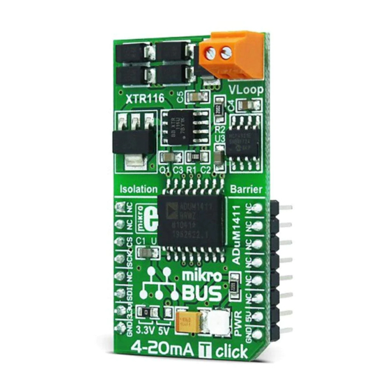
4-20mA T
click
1. Introduction
4-20mA T Click™ is an accessory board in
mikroBUS™
form factor. It's a compact and
easy solution for adding 4-to-20mA industry
standard communication protocol to your
design. It features
ADuM1411
Quad-chanel
MCP4921
digital isolator,
12-bit DAC as well
as
XTR116
4-20mA current loop transmitter.
4-20mA T Click™ communicates with target
mikroBUS™
board microcontroller via three
SPI lines (SDI, SCK, CS). The board is designed
to use 3.3V and 5V power supply. LED diode
indicates the presence of power supply.
Arrow.com.
Downloaded from
2. Soldering the headers
Before using your click board™, make sure
to solder 1x8 male headers to both left
and right side of the board. Two 1x8 male
headers are included with the board in
the package.
2
Turn the board upside down so that
bottom side is facing you upwards. Place
shorter parts of the header pins in both
soldering pad locations.
1
3
Turn the board upward again. Make sure
to align the headers so that they are
perpendicular to the board, then solder the
pins carefully.
3. Plugging the board in
Once you have soldered the headers your
board is ready to be placed into desired
mikroBUS™ socket. Make sure to align the
cut in the lower-right part of the board
with the markings on the silkscreen at the
mikroBUS™ socket. If all of the pins are
aligned correctly, push the board all
the way into the socket.
4. Essential features
4-20mA T Click™ with it's ADuM1411,
MCP4921 and XTR116 IC's is ideal for
using in field of industrial process control
and test systems. It serves as interface
between sensors or instruments (connected
to microcontroller) and controlled peripherals
in industrial standard current loop. The
board receives the input digital signal from
the microcontroller and sets the output loop
current (4-20mA).
click
BOARD
www.mikroe.com
4-20mA T click Manual
ver. 1.00
0 100000 022139
Advertisement
Table of Contents

Related Manuals for MicroElektronika click BOARD 4-20mA T

Summary of Contents for MicroElektronika click BOARD 4-20mA T
- Page 1 2. Soldering the headers Before using your click board™, make sure to solder 1x8 male headers to both left and right side of the board. Two 1x8 male headers are included with the board in the package. 4-20mA T click 1.
- Page 2 6. SMD Jumper 5. 4-20mA T Click™ Board Schematic VCC_iso There is one zero-ohm SMD jumper J1 which is used to select whether 3.3V or 5V power 100nF 100nF supply is used. Jumper J1 is soldered in 3.3V GND_iso position by default. VCC_iso +3V3 VCC_iso...
Need help?
Do you have a question about the click BOARD 4-20mA T and is the answer not in the manual?
Questions and answers