Table of Contents
Advertisement
Quick Links
● ● ● ●
W ARNING :
To prevent personal injury or equipment damage, only qualified technicians /operators
should install, operate or service this device.
● ● ● ●
C AUTION :
Megger and high potential test equipment should not be used.
Incorrect use of such equipment could damage components contained in the regulator.
:
1. APPLICATION
2. FEATURES :
2.1. Available for low resistance exciter filed.
2.2. Under frequency protection circuit.
When the generator frequency drops below the set point, generator output voltage is decreased with
the curve proportional to the frequency.
2.3. Over excitation
When the generator excitation field voltage exceeds 85Vdc, AVR output shut down to protect the
generator winding coil from burning out.
2.4. Starting engine generator set, if the residual voltage remains on the stator winding of generator,
AC output voltage is built up rapidly.
2.5. Durable under dust, damp and vibration.
2.6. Response time, below 25ms(1.5cycles)
3. SPECIFICATIONS
3.1. Input : 190~277Vac, 1
3.2. Output :
MODEL
AVR - 125
3.3. Sensing : 1
Φ
Φ
1
3.4. Exciter field resistance : 2ohms to 100ohms
3.5. External voltage adjust rheostat : 1
3.6. Voltage adjust range
Coarse adjusting (by internal rheostat)
Fine adjusting (by external rheostat)
3.7. voltage regulating accuracy
3.8. Voltage build up condition internally and automatically raised by the residual voltage from the
Generator stator winding (minimum 3Vac)
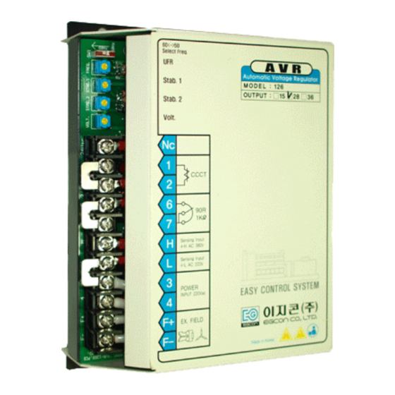
AUTOMATIC VOLTAGE REGULATOR
(MODEL : AVR-126)
AVR 125 is voltage regulator to control brushless generator output by regulating
the current into the generator exciter field.
Φ
, 50/60Hz, Burden 650VA (terminal 3-4)
VOLTAGE
125Vdc
, 190 ~ 240Vac (220V sensing – terminal 4-3)
, 380 ~ 400Vac (380V sensing – terminal 4-E1)
±
1 .0%
CURRENT
Maximum current (for 1min.) - 20A
㏀
, 2W (out of supply scope)
±
1 2.5%
±
5 %
1
REMARKS
15A
continuous
Advertisement
Table of Contents

Related Manuals for Egcon AVR-126

Summary of Contents for Egcon AVR-126
- Page 1 AUTOMATIC VOLTAGE REGULATOR (MODEL : AVR-126) ● ● ● ● W ARNING : To prevent personal injury or equipment damage, only qualified technicians /operators should install, operate or service this device. ● ● ● ● C AUTION : Megger and high potential test equipment should not be used.
- Page 2 3.9. Over excitation shut down : when exciter field voltage exceeds the following, AVR output is removed. Otherwise, exciter field voltage keeps on over 85 ± 5 Vdc for 10sec, or instantaneously it exceeds 100Vdc. After shutdown, to reset the regulator, generator set should be stopped or the power input to the AVR Should be interrupted for more than 20seconds.
- Page 3 ▶ Remote voltage adjust Remove the jumper from the terminal 6 and 7, and connect the remote voltage adjust potentiometer (rheostat) to the terminals 6 and 7 as specified. ▶ Sensing voltage Generator voltage sensing is single-phase 220Vac or 380Vac. It can be selected in accordance with generator output voltage (or rated voltage) as follows, *380V sensing (terminal 4-E1) ;...
- Page 4 ▶ turning CW increase the level for damping generator transient output voltage. ▶ turning CCW decrease damping level to cause under damping 6.6. Choice frequency switch depending on generator frequency (SW1) This option protects generator and AVR by decreasing generator output voltage if it reduces generator frequency.
- Page 5 6) Stop the engine and remove battery and push button. 7) Reconnect all wires. 8) Start engine and check the output voltage. ● ● ● ● N OTE To take flash exciting without engine running, keep the button on a pushed condition to close the flash exciting circuit for 30sec.
- Page 6 9. TROUBLE SHOOTING SYMPTOM CAUSE ACTION Residual voltage at regulator Check wiring diagram for proper power input wires 3 & 4 below 3Vac. Connections. Flash generator field. Refer to 7.FLASH EXCITING section in generator manual. Field leads F+, F- not connected. Connect field lead F+, F-.
- Page 7 Incorrect connections. Check wiring diagram for proper connections. Incorrect sensing voltage connection can cause output voltage low-no adjustment. Voltage adjust turned down. Rotate voltage adjust CW until desired Output Voltage Low voltage is reached. Remote voltage adjust is turned down. Rotate remote voltage adjust CW until desired voltage is reached.
Need help?
Do you have a question about the AVR-126 and is the answer not in the manual?
Questions and answers