Table of Contents
Advertisement
Quick Links
Manual for Systems and Procedures
ITALAB reserves the right to modify and change the information contained in this document without previous notice.
Ediz./Rev.
ATLAS1000‐AR144/00
Reference Manual
Italian Technology of Broadcast
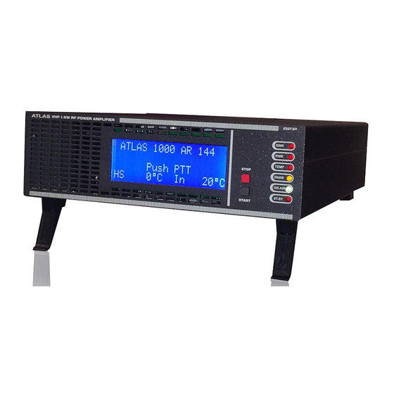
ATLAS 1000 AR 144
Via Casale 3/A
20144 Milano Italy
Phone: (39) 02 90389417
Fax: (39) 02 23168389
E‐mail: info@italab.it
WorldWide web:
www.italab.it
Date
Reason
01/01/2016
Second Edition
ATLAS 1000 AR144
Approved by:
Micalizzi ‐ Scandelli
Page 1 of 41
Advertisement
Table of Contents

Summary of Contents for ITB ATLAS 1000 AR144
- Page 1 WorldWide web: www.italab.it ITALAB reserves the right to modify and change the information contained in this document without previous notice. Ediz./Rev. Date Reason Approved by: 01/01/2016 Second Edition Micalizzi ‐ Scandelli ATLAS1000‐AR144/00 Reference Manual ATLAS 1000 AR144 Page 1 of 41...
- Page 2 Warranty Service The ATLAS 1000 AR144 is a highly reliable device. Nevertheless, as it happens for all advice active 24 hours over a number of years, some malfunctions may take place. Repair of the modules within the amplifier is very difficult on site, it is recommended you contact...
- Page 3 Power Supply Tipical Display Screens Power On Transmission Start Stop Sequence Alarm Messages Allarm PWR Allarm SWR Temperature Alarm User Program Programming clock Programming language Programming name Schemes and material list Reference Manual ATLAS 1000 AR144 Page 3 of 41...
- Page 4 Step 3 If the victim cannot breathe properly, close their nose and start artificial breathing. Give them 2 deep breaths, the victim’s chest will inflate if you supply sufficient air. Reference Manual ATLAS 1000 AR144 Page 4 of 41...
- Page 5 Areas between foot or hand fingers, ears to the head skin, lower surface of the arm with the chest skin, groin folds etc. • Transport immediately, if possible, to a medical facility or call for help immediately! Reference Manual ATLAS 1000 AR144 Page 5 of 41...
- Page 6 DO NOT TRY TO REPAIR ATLAS 1000 AR144 Maintenance, repair and substitution of internal parts must be performed only by qualified ITB personnel. FUSES In case the fuses break, after having removed the cause of the problem, please substitute them with the same kind.
- Page 7 The maintenance and repair can be made only by authorized ITALAB staff. • Before removing the ATLAS 1000 AR144 cover, please turn off the power switch. This can be found on the rear of the device. The power cable must be removed from the electric socket.
-
Page 8: Device Description
The information is addressed to a system manager, expert in the knowledge of high‐performance transmission systems. ATLAS 1000 AR144 is a solid state amplifier which operates in the 144 MHz frequency ranges. The RF part is made up of an amplifier unit ( MD 1200P AR 144 ) able to supply 1200 Watt power in continuous service. -
Page 9: Technical Features
Power Supply 210 – 270 Vac Power absorbed by the antenna ≤ 1500W@ 1KW 144 MHz Dimensions (mm ) H =95, P = 400, L= 300 Weight (mm) 6,5 Kg ÷10% Reference Manual ATLAS 1000 AR144 Page 9 of 41... -
Page 10: Front Panel
By pressing the button, the device will go in stand‐by mode and the pallet will remove auxiliary output power from the device. START BUTTON: By pressing the button, the device will set the pallet in transmission mode and auxiliary output power will be supplied. Reference Manual ATLAS 1000 AR144 Page 10 of 41... -
Page 11: Rear Panel View
A.C. Line input (240 Vac.) RF Output Connector RF Input Connector Cooling Air Exit RF section A.C. Auxiliary Commanded Voltage Exit (TX), optional RCA Connector (PTT input) AC/DC Power Supply ventilation Air Exit Reference Manual ATLAS 1000 AR144 Page 11 of 41... -
Page 12: Internal View
Relay input radio frequency transmitter Relay output radio frequency antenna RF output connector RF box interface RF box input connector switching AC/DC power supply Power supply hot air output fan General power switch Reference Manual ATLAS 1000 AR144 Page 12 of 41... - Page 13 The RF connection cable between the exciter and the amplifier must be connected. Please ensure Power reaching the amplifier is not higher than 2 Watts. An excessively high input power or high initial peaks will damage the device. Reference Manual ATLAS 1000 AR144 Page 13 of 41...
-
Page 14: System Start-Up
You must be absolutely certain that the floor will not flood in case of heavy rain. Also humidity can cause condensation within the amplifier. This can cause destructive electric arches during on/off power phases of the system which could cause damage not covered by the warranty. Reference Manual ATLAS 1000 AR144 Page 14 of 41... - Page 15 Italian Technology of Broadcast SYSTEM BLOCK DIAGRAM INTERNAL CONNECTIONS DIAGRAM Reference Manual ATLAS 1000 AR144 Page 15 of 41...
-
Page 16: Circuit Description
Within the card there are various switching DC/DC converters. These produce the low tension power supply from the principal 48V for all electronic circuits and existing elements within the device. Reference Manual ATLAS 1000 AR144 Page 16 of 41... -
Page 17: Analog Card
The module performs an efficient 240 Vac input voltage conversion to the 48Vdc power supply voltage for the RF pallet CPU card. High efficiency of the device means very little heat is created during this regulation process. Reference Manual ATLAS 1000 AR144 Page 17 of 41... - Page 18 Italian Technology of Broadcast TYPICAL DISPLAY SCREENS The ATLAS 1000 AR144 is supplied with an excellent display with 4 rows of 20 characters. This guarantees optimal view of the messages. 1.1 START TRANSMISSION The following text appears on start‐up of the amplifier after turn on or after release of the PTT, the device moves to the waiting starting state.
- Page 19 TX and the auxiliary jack (optional) on the rear panel. At the end of the sequence returns to the state of "waiting transmission start" Reference Manual ATLAS 1000 AR144 Page 19 of 41...
-
Page 20: Alarm Messages
After a few seconds, the CPU runs the sequence. If at the end of the sequence the SWR returns to normal parameters, the transmission will continue, if not, it will return to the alarm cycle. Reference Manual ATLAS 1000 AR144 Page 20 of 41... - Page 21 To restart the system, the Amplifier must be turned off and on again through the general power switch. Reference Manual ATLAS 1000 AR144 Page 21 of 41...
-
Page 22: User Program
When the correct password is entered the message appears on the display R O G R After pressing the start button the message appears on the display O G R A M M I Reference Manual ATLAS 1000 AR144 Page 22 of 41... - Page 23 A M M I In this situation, if you press the stop button you go to the next menu (LANGUAGE programming) while if you press the start button you enter the "CLOCK programming" menu. Reference Manual ATLAS 1000 AR144 Page 23 of 41...
-
Page 24: Clock Programming
In this situation, if you press the start button you will return to the clock programming menu, while if yes press the stop button to enter the language programming menu and the message appears on the display Reference Manual ATLAS 1000 AR144 Page 24 of 41... -
Page 25: Language Programming
For English: N G U A O G R M M I N G L For French: N G U A O G R M M I Reference Manual ATLAS 1000 AR144 Page 25 of 41... - Page 26 In this situation, if you press the start button you will return to the language programming menu while if yes press the stop button to enter the menu to change the name that appears on the first line of the display e the message appears on the display Reference Manual ATLAS 1000 AR144 Page 26 of 41...
-
Page 27: Name Programming
In questa situazione se si preme il pulsante di start si ritorna nel menù programmazione nome mentre se si preme il pulsante di stop si entra nel menu uscita programmazione e sul display appare la scritta Reference Manual ATLAS 1000 AR144 Page 27 of 41... -
Page 28: Exit Programming
In this situation, if you press the start button, you go back to the ”waiting for transmission start” status while if you press the stop button, you enter the menu to exit programming. To make the changes made, it will be necessary to turn the device off and on again. Reference Manual ATLAS 1000 AR144 Page 28 of 41... - Page 29 Italian Technology of Broadcast SCHEMATICS and BILL OFF MATERIALS RF BOARD Reference Manual ATLAS 1000 AR144 Page 29 of 41...
-
Page 30: Cpu Board
Italian Technology of Broadcast CPU BOARD Reference Manual ATLAS 1000 AR144 Page 30 of 41... - Page 31 Italian Technology of Broadcast Reference Manual ATLAS 1000 AR144 Page 31 of 41...
- Page 32 Italian Technology of Broadcast Reference Manual ATLAS 1000 AR144 Page 32 of 41...
- Page 33 Italian Technology of Broadcast Reference Manual ATLAS 1000 AR144 Page 33 of 41...
- Page 34 Italian Technology of Broadcast Reference Manual ATLAS 1000 AR144 Page 34 of 41...
- Page 35 Italian Technology of Broadcast Reference Manual ATLAS 1000 AR144 Page 35 of 41...
- Page 36 Italian Technology of Broadcast Reference Manual ATLAS 1000 AR144 Page 36 of 41...
- Page 37 Italian Technology of Broadcast Reference Manual ATLAS 1000 AR144 Page 37 of 41...
-
Page 38: Led Board
Italian Technology of Broadcast LED BOARD Reference Manual ATLAS 1000 AR144 Page 38 of 41... - Page 39 Italian Technology of Broadcast Reference Manual ATLAS 1000 AR144 Page 39 of 41...
-
Page 40: Analog Board
Italian Technology of Broadcast ANALOG BOARD Reference Manual ATLAS 1000 AR144 Page 40 of 41... - Page 41 Italian Technology of Broadcast Reference Manual ATLAS 1000 AR144 Page 41 of 41...
Need help?
Do you have a question about the ATLAS 1000 AR144 and is the answer not in the manual?
Questions and answers