Table of Contents
Advertisement
Quick Links
Advertisement
Table of Contents

Summary of Contents for Trio TPS
- Page 1 TPS: Teach programming system...
- Page 2 SAFETY WARNING During the installation or use of a control system, users of Trio products must ensure there is no possibility of injury to any person, or damage to machinery. Control systems, especially during installation, can malfunction or behave unexpectedly.
-
Page 3: Table Of Contents
The device ......................1 2.1 Introduction ............................. 1 2.2 Technical specifications ........................3 Declaration of conformity ..................5 TPS: Teach Programming System ................6 4.1 Virtual Teach Pendant casing ......................6 4.2 Keypad ............................. 7 4.3 Home screen ..........................10 4.4 Warning / error window ........................ - Page 4 Settings ......................54 6.1 About ............................. 54 6.2 IO configuration ..........................55 Error and warning codes ..................56 7.1 Axis status codes ..........................56 7.2 Robot status codes ......................... 56 7.3 TPS system codes ........................... 57 7.4 RPS Architecture codes ........................58...
-
Page 5: Tps Teach Pendant
The Teach Programming System allows programming the robot in a managed and safe environment, using a real or virtual system. The pendant is based around Trio’s UNIPLAY HMI and can be used as a “real” or “virtual” on-screen pendant. The system includes extensive software and preconfigured motion control functions, which permit the controlling of all standard types of robot with reduced development time. - Page 6 A virtual teach pendant has been developed that, along with other Motion Perfect robot tools, provides a virtual robot environment to design and debug robot solutions over PC. Figure 2-2: Virtual pendant TPS: Teach Programming System...
-
Page 7: Technical Specifications
2.2 Technical specifications Figure 2-3: teach pendant device specs TPS: Teach Programming System... - Page 8 Figure 2-4: Junction Box RPS has to be configured depending on what inputs had been used to connect the junction box with the controller. Refer to section IO configuration to set the inputs numbers into the system. TPS: Teach Programming System...
-
Page 9: Declaration Of Conformity
- Power frequency magnetic field immunity test. The notified body: Compliance Certification Services Inc. Kunshan Laboratory, Kunshan City, Jiangsu, China, duly issued the CE EMC Test certificate. Report Number: C180913E14-ET Dated: 27 September 2018 TPS: Teach Programming System... -
Page 10: Tps: Teach Programming System
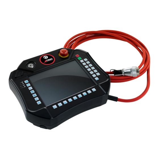
4 TPS: Teach Programming System 4.1 Virtual Teach Pendant casing Virtual Teach Pendant with compact casing and key switch, E-Stop and demand buttons can simulate the same behaviour like real Teach Pendant. Key switch, E-Stop and demand buttons can be configured with a virtual or real outputs. -
Page 11: Keypad
Enter the variable list page Prompt the list of programs in the current project Program list Program editor Enter the program editor page Positions Prompt axis position window Messages / Log Prompt the messages and log interface TPS: Teach Programming System... - Page 12 Execute the selected program forward or backward execution Operation mode Change the program running mode between step and continuous mode Jog speed minus Decrease the global jog speed Jog speed plus Increase the global jog speed TPS: Teach Programming System...
- Page 13 Jog axis negative Under servo ON condition, jog axis backward Jog axis positive Under servo ON condition, jog axis forward Extra axes page Change to second axis page if the robot have more than six axis TPS: Teach Programming System...
-
Page 14: Home Screen
4.3 Home screen System status windows will show warnings and errors that happens in every robot axis. It will show the axis number, error code and the message itself. Figure 4-5: Home page TPS: Teach Programming System... -
Page 15: Warning / Error Window
The whole group of messages can be cleared by clicking trash button. A special log entry is stored every time the controller is powered up, such as: 600:00014@1ms[0.05 2.0296000 $0000 $0c000003] TPS: Teach Programming System... -
Page 16: Drive
To reset it to its normal status, VR(DriveError) has to be = 0. To trigger the events, VR(DriveMessageTrigger) has to be incremented. The messages have to be stored in VRs and have been divided by axis: VR(DriveMessageAxis1), VR(DriveMessageAxis2), VR(DriveMessageAxis3), VR(DriveMessageAxis4), VR(DriveMessageAxis5) and VR(DriveMessageAxis6). TPS: Teach Programming System... - Page 17 'press refresh button -> VR(DriveErrorReset) = 1 VR(driveerrorreset) = THEN VR(driveerrorreset) = 'Reset logic: 'error drive 1 persist VR(drivemessageaxis1) = "Error in drive 1 persist" 'error drive 3 cleared VR(drivemessageaxis3) = 'Trigger drive errors VR(drivemessagetrigger) = VR(drivemessagetrigger) + ENDIF TPS: Teach Programming System...
-
Page 18: Speed
Figure 4-8: Drive error window 4.5 Speed Jog speed can be set in percentages by Speed window. Figure 4-9: Speed window TPS: Teach Programming System... -
Page 19: Jog Modes
Status bar will show the robot, tool, object frame and robot frame selected. All of them are selectable in their specific pages. Figure 4-10: status bar It is also shown the status of pendant (manual, auto, disabled), Estop, Servo and Demand buttons. Manual, Auto, Disabled mode Estop released, Estop pressed Servo ON, Servo OFF TPS: Teach Programming System... -
Page 20: User Levels
Level 4 Status and log Jog Speed Jog Modes GTAs Tools Dimensions Tools Collision Object Frames Robot Frames Collision Objects Project Manager Program Editor(Debug Buttons) Program Editor(Program edition Buttons) Program Types and Projects Instructions Set Settings TPS: Teach Programming System... - Page 21 Level 1: level1 Level 2: level2 Level 3: level3 Level 4: level4 Characters allowed are the ASCII table. To reset all passwords to default values, COORDINATOR_DATA(68) instruction has to be executed over the terminal through Motion Perfect. TPS: Teach Programming System...
-
Page 22: Main Menu
4.9 Main menu Main menu button will drop the main menu: Projects manager and program editor GTA page Tools and Frames menu Applications menu Inputs / outputs page Setting page Projects: Project manager window Program editor page TPS: Teach Programming System... - Page 23 Applications: Palletizer page Tools, frames and collision objects: Object Frames page Robot Frames page Tools menu Collision Objects page TPS: Teach Programming System...
- Page 24 Tools dimensions and collision: Tools dimension page Tools collision page TPS: Teach Programming System...
-
Page 25: Gtas
It will save the table in the program “ROBOT_GLOBAL_TARGETS” (the program will be overwritten with the new values). If a GTA is set by another program while GTA page is active, it is possible to refresh the table by clicking refresh button. TPS: Teach Programming System... - Page 26 That entry will become empty in controller volatile memory and GTAs screen but controller program will still having the entry until save button is pressed. Zero entries check box will collapse or expand the empty entries for a more compact representation. Figure 4-15: Edit GTAs window TPS: Teach Programming System...
-
Page 27: Tools Dimensions
It will save the table in the program “ROBOT_TOOLS_AND_FRAMES” (the program will be overwritten with the new values). If a Tool is set by another program while Tools page is active, it is possible to refresh the table by clicking refresh button. TPS: Teach Programming System... - Page 28 Calibrate Calibrate button will lead to Calibrate page. In this page it will be possible to calculate the dimensions of a tool performing a calibration procedure. Figure 4-17: Tool calibration page TPS: Teach Programming System...
- Page 29 By pressing one of the grey tools images the values will be saved for that position and it will become green, showing that position has been stored. Figure 3-18: Tool calibration save position window TPS: Teach Programming System...
- Page 30 A deviation value (Serror) is displayed as well. It can be used as an indication for the quality of the point and the operator can decide to recapture some of the points in order to improve the calibration. TPS: Teach Programming System...
- Page 31 Figure 4-20: Tool calibration process done By pressing accept button the tool data will be stored to the controller and the new values will appear in Tools page. Figure 4-21: Tools page calibration process done TPS: Teach Programming System...
-
Page 32: Tools Collision
31 definitions is available for use to all programs. A unique name can be assigned to each tool to be used to identify and reference it in programs. For more information please, refer to RPS manual. Figure 4-22: Object Frames page TPS: Teach Programming System... -
Page 33: Object Frames
All the changes will be done in volatile memory. It is possible to save the whole table in flash memory by clicking save button. It will save the table in the program “ROBOT_TOOLS_AND_FRAMES” (the program will be overwritten with the new values). If an Object TPS: Teach Programming System... - Page 34 First point should be at the base or the origin of the object coordinate system. Second point should on the X axis of the object coordinate system. Third point should on the Y axis of the object coordinate system. Figure 4-24: construct Object Frame window TPS: Teach Programming System...
- Page 35 Object Frame screen but controller program will still have the entry until save button is pressed. Zero entries check box will collapse or expand the empty entries for a more compact representation. Figure 4-25: Edit Object Frames window TPS: Teach Programming System...
-
Page 36: Robot Frames
“ROBOT_TOOLS_AND_FRAMES” (the program will be overwritten with the new values). If a Robot Frame is set by another program while Robot Frames page is active, it is possible to refresh the table by clicking refresh button. TPS: Teach Programming System... - Page 37 Robot Frame screen but controller program will still having the entry until save button is pressed. Zero entries check box will collapse or expand the empty entries for a more compact representation. TPS: Teach Programming System...
-
Page 38: Collision Objects
All the changes will be done in volatile memory. It is possible to save the whole table in flash memory by clicking save button. It will save the table in the program “ROBOT_TOOLS_AND_FRAMES” (the program will be overwritten with the new values). If a Collision TPS: Teach Programming System... - Page 39 It is possible to delete a Collision Object by clicking in delete button. That entry will become empty in controller volatile memory and Collision Objects screen but controller program will still having the entry until save button is pressed. TPS: Teach Programming System...
-
Page 40: Applications: Palletizer
This function can create a palletizer. It separates the building process into several steps. The first step builds a plane with size of three dimensions. Figure 4-30: pallet configuration window. The second step is to design item size and position. The dimension of item and position of tool target. TPS: Teach Programming System... - Page 41 Figure 4-31: item configuration window The third step is to design number items of each layer. Figure 4-32: layer configuration step1 window TPS: Teach Programming System...
- Page 42 The objects on each layer can be organised by clicking Edit in Layer configuration page. Figure 4-33: item organiser window TPS: Teach Programming System...
- Page 43 The next step can put items on a virtual tray. Figure 4-34: layer configuration step2 window The Generate Points button can define the start number from GTAs list. There is another application related to this palletizer application in pendant edit program list. TPS: Teach Programming System...
-
Page 44: Projects And Programs
If USB stick button is selected, its content is shown and programs and projects can be loaded or deleted. Only one project with multiples programs can be stored in controller memory. For multiples projects use an USB stick. Projects have to be in root directory organised in folders. TPS: Teach Programming System... -
Page 45: Program Editor
Debug buttons: Run selected program. Stop Stops selected running program. Stops all currently running programs and empties all Motion stop move buffers causing all motion to stop. Break point Toggle breakpoint on selected line. Program edition buttons: TPS: Teach Programming System... -
Page 46: Multi-Line Selection
5.4 Default move values Default move values can be accessible by the left lower corner link where, in this case, says MOVEJ S:=50 T:=TO_default O:=OF_default. These values will be used by teach instruction explained below. TPS: Teach Programming System... -
Page 47: Program Types And Projects
It shows in a list all robot programs available in controller flash memory. There are two different robot programs: Robot Programs (.ROB file extension) and Robot Basic Programs (.RBS file extension). Figure 5-4: program list window TPS: Teach Programming System... - Page 48 Both have the same functionality but robot programs can only contain the list of functions available from pendant. Also, TPS can only edit robot programs. Robot basic programs can only be run and debugged. To select what type of robot program will be shown in the program list just simply press the buttons:...
-
Page 49: Instructions Set
MOVEC is used to move the robot from one point to another along a circular path. All axes reach the destination position at the same time. This type of move needs a middle point in the curve and the end point. TPS: Teach Programming System... -
Page 50: Base
If a GTA is already selected, Teach button will overwrite its value with the current robot position. 5.6.3 Base The BASE command is used to direct all subsequent motion instructions and robot parameter read/writes to a particular robot. It is also used to select external axes. TPS: Teach Programming System... -
Page 51: Gosub
With a label RETURN instruction is inserted automatically as well. RETURN instruction can be inserted as its own by selecting RETURN radio button on LABEL window. Figure 5-11: Label instruction It is recommended to insert STOP instruction above any LABEL-RETURN structure to avoid execution errors. TPS: Teach Programming System... -
Page 52: Stop
The type of possible variables that can be declare are the next ones: Boolean: 1bit binary value (TRUE or FALSE). Float: 64bit floating point number. Integer: 64bit signed integer value. String: ASCII text (1024 characters maximum). String data type require size as an extra parameter. TPS: Teach Programming System... - Page 53 VR value. If the selected variable is STRING datatype it will display a QWERTY keyboard window at the moment of setting its value. Figure 5-16: Variable list window Figure 5-15: Set variable value window TPS: Teach Programming System...
-
Page 54: Wait
If multiple expressions are valid then the first will have its instructions executed. If no expressions are valid and an ELSE is present the instructions under the ELSE will be executed. Figure 5-19: While...Wend structure window Figure 5-20: Repeat...Until structure window TPS: Teach Programming System... - Page 55 It is a wizard that helps users set the condition for structure instructions. The conditions are built in the following format: variable - relational operator – variable logical operator variable - relational operator - variable … Figure 5-24: Condition builder window Figure 5-22: Condition builder window Figure 5-23: relational operators TPS: Teach Programming System...
-
Page 56: Apps
FOR...NEXT loops can be nested up to 8 deep in each program. Figure 5-26: For...Next structure window 5.6.11 APPS This application can design a conveyer system compare with former palletizer system. There are several blocks to determine some parameters needed in the conveyer and palletizer system. TPS: Teach Programming System... - Page 57 Tool Output: The output tool like gripper OF item: Offset point on the conveyer OF pallet: Offset point on the pallet Sensor input: Vision or light sensor input of system Middle: The middle point of tool. TPS: Teach Programming System...
-
Page 58: Settings
6 Settings 6.1 About In this section it is shown information about the version of the system: controller version, serial number, controller type, Uniplay version and RPS version. Figure 6-1: About page TPS: Teach Programming System... -
Page 59: Io Configuration
6.2 IO configuration Every system has different IO configuration. In this page it will be possible to address the different physical IOs with RPS. Figure 6-2: IO configuration TPS: Teach Programming System... -
Page 60: Error And Warning Codes
AXIS_FS_LIMIT active AS_17 AXIS_RS_LIMIT active AS_21 FEC 26: Robotics runtime 1 hour free limit. Reset the controller 7.2 Robot status codes RS_0 WORLD_FS_LIMIT active RS_1 WORLD_RS_LIMIT active RS_2 ROBOT_FS_LIMIT active RS_3 ROBOT_RS_LIMIT active RS_4 TCP_FS_LIMIT active TPS: Teach Programming System... -
Page 61: Tps System Codes
RS_10 Elbow singularity RS_11 Max speed limit RS_12 Robot collided 7.3 TPS system codes TE_0 Jog attempted out of Manual mode. Select Manual mode TE_1 Jog attempted while E-Stop is pressed. Release E-Stop and enable robot TE_2 Jog attempted without enable the robot. Press demand button... -
Page 62: Rps Architecture Codes
Error status because SYSTEM_ERROR. Press reset button to clear the error RA_3 Error status because MOTOR output is off. Press reset button to clear the error RA_4 Error status because WDOG turned off unexpectedly. Press reset button to clear the error TPS: Teach Programming System...