SEI Industries Bambi Max BBXHL4000PF Service Manual
Hide thumbs
Also See for Bambi Max BBXHL4000PF:
- Operation manual (28 pages) ,
- Operation manual (29 pages)
Advertisement
Quick Links
Advertisement

Related Manuals for SEI Industries Bambi Max BBXHL4000PF


Summary of Contents for SEI Industries Bambi Max BBXHL4000PF
- Page 1 BAMBI MAX (4453–7590 MODELS) SERVICE MANUAL 2016 VERSION D Photo courtesy of Dan Sweet...
- Page 2 Phone: (604) 946-3131 Fax: (604) 940-9566 E-Mail: seisales@sei-ind.com Website: www.sei-ind.com USA Patent # 9,265,977 Australia Patent AU2012201273 Canada Patent Pending COPYRIGHT © 2016 SEI INDUSTRIES LTD. ALL RIGHTS RESERVED – We Engineer Solutions 2016 Bambi MAX Service Manual Models 4453-7590 (Version D)
- Page 3 Table of Contents Section 1: Introduction Bambi MAX (Models 4453–7590) .................1 Valve System ........................2 System Overview ....................2 System Description ..................2 Section 2: Deploying the Bambi MAX Deployment Instructions ....................6 Attaching to the Cargo Hook ................6 Head Orientation ....................6 Connecting Power ..................7 Using Longlines ....................7 Instant Deployment System (IDS) ................10 Section 3: Using Accessories...
- Page 4 Section 7: Valve Maintenance MAX Valve Repair and Replacement .................26 Linkage Adjustment ..................26 Valve Removal .....................26 Valve Installation ..................28 Bambi MAX Seal Replacement ..............30 Drive Cable Replacement ................35 Changing the Guide Bushings ..............39 Section 8: Repair Quick Guide Overview of Repair Categories ...................40 Category 1: Safety ..................40 Category 2: Operational ................40 Category 3: Monitor ..................40...
- Page 5 Section 10: Specifications and Parts Capacity and Weight Specifications ................67 Bambi MAX Capacity and Weight Specifications .........67 Bambi MAX with PowerFill Capacity and Weight Specifications ....67 Parts Listings ......................68 Bambi MAX Valve 25” Shell Assembly, Models 4453-5566 ......68 Bambi MAX Valve 25" Shell Assembly, Models 6578-7590 ......69 Bambi MAX Valve 25"...
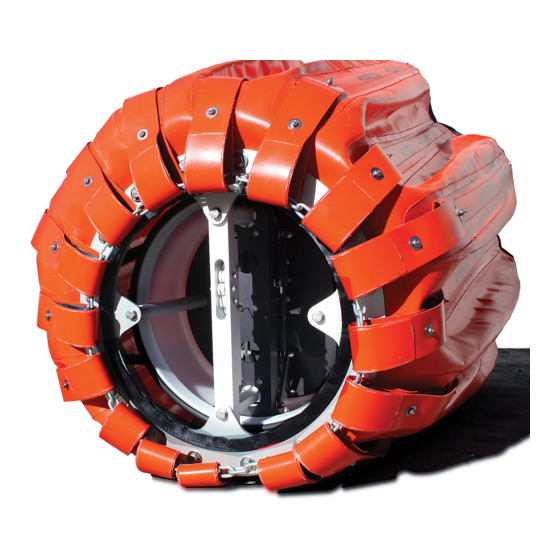
- Page 6 Bambi MAX inside bucket. MAX. There are several other models of buckets available from SEI Industries. These include Bambi MAX model series 1518-3542 and series HL4000-HL9800. In addition, a number of accessories and enhancements are also available including the PowerFill system, Power Pack with hand grip (for valve only), Sacksafoam and Marine Recovery Device.
- Page 7 Valve System Section 1: Introduction Valve System System Overview The Bambi MAX uses a tubular type valve with seals located on the top and bottom of the tube. When in the default closed position, the seals make contact with top plate and bottom ring of the valve assembly. When in the open position, the tube is raised allowing water to flow between the bottom of the tube and the base ring and then through the opening in the base ring.
- Page 8 Valve System Section 1: Introduction When the motor and cable drum is rotated clockwise, the drive cable pulls up on the lift bar, opening the valve. When the motor and cable drum is rotated counter-clockwise, the other end of the drive cable pulls down on the lift bar via the deflector sheaves, closing the valve.
- Page 9 Valve System Section 1: Introduction Valve position feedback to the controller is provided by a sensor cam and two sensors. The sensor cam is located on the front of the cable drum and rotates with the motor and cable drum. The sensors are located in the controller enclosure.
- Page 10 Valve System Section 1: Introduction The controller has an internal motor protection system to prevent the motor from being overloaded. When excessive current flows to the motor due to a stalled condition, the motor protection device activates. When activated, the device isolates the motor from the power source. but does not remove power from the rest of the controller.
- Page 11 Deployment Instructions Section 2: Deploying the Bambi MAX Section 2: Deploying the Bambi MAX Deployment Instructions Attaching to the Cargo Hook Caution The Bambi MAX may not be suitable for a direct hook-up to the cargo hook. The actual hook-up will be different for various aircraft and operators must comply with all instructions and bulletins supplied by the aircraft manufacturer.
- Page 12 Deployment Instructions Section 2: Deploying the Bambi MAX Connecting Power The power requirement to control the Bambi MAX valve is 5 amps, 24/28 VDC. The Bambi MAX comes with a three-conductor, 16-gauge control cable that comes from the valve to 3' above the head. Attached to the end of the cable is a male waterproof Nema 5-15 electrical plug (the female receptacle for the helicopter is attached).
- Page 13 Deployment Instructions Section 2: Deploying the Bambi MAX We do not recommend using zip ties to attach wiring/conduit as this tends to damage the cover and longline. When attaching conduit, allowances must be made for any stretch in the load bearing line and this must be taken into account when attaching to ensure that the terminations are not released from the belly, bucket or hook, etc.
- Page 14 Deployment Instructions Section 2: Deploying the Bambi MAX Overall lengths of Bambi MAXs with standard rigging are provided in this manual. Before using the Bambi MAX, check for the maximum total length. To determine this length, measure the distance from the cargo hook to the front tip of the tail rotor on the helicopter you will be using and subtract 6”...
- Page 15 Instant Deployment System (IDS) Section 2: Deploying the Bambi MAX Instant Deployment System (IDS) The instant deployment system uses a hub and spoke mechanism to automatically expand the mouth of the bucket as soon as the weight of the Bambi MAX is taken up by the suspension cables. When the bucket is full, the IDS deployment cable and hub restrainer cables should be slack as they should not bear any load.
- Page 16 Using PowerFill Section 3: Using Accessories Section 3: Using Accessories Using PowerFill Overview The PowerFill system is comprised of two electrically driven pumps which have a combined output of 900gpm (56 L/s). The system allows a helicopter to get partial or complete fills from a range of previously inaccessible shallow water sources including streams, canals, ponds and low profile dip tanks.
- Page 17 Using PowerFill Section 3: Using Accessories Electrical Requirements The pumps require a 28VDC power source capable of supplying 90 amperes of current. This supply must be from the aircraft non-essential bus or from a transformer / rectifier unit (TRU). The installation shall be done in accordance with FAA Advisory Circulars AC43.13-1B and AC43.13-2A and any applicable aircraft manufacturer's instructions.
- Page 18 Using Foam Section 3: Using Accessories Caution Do not run the pump if it is submerged to a depth of 10 ft. (3 m) or more. Do not submerge the bucket to a depth of more than 20 ft. (6.1 m) when performing conventional dip fills (pump off). Important Note The filter screens are designed to filter out objects large enough to damage the pump impellers and to prevent weeds and debris from clogging the pump intakes.
- Page 19 Section 3: Using Accessories Sacksafoam Foam Injection System The Sacksafoam is SEI Industries’ advanced foam dispensing system for use with the Bambi MAX. This system, exclusive to the Bambi, allows foam to be dispensed into the bucket in route from the filling source to the fire site.
- Page 20 Bambi Mobility Sled Section 3: Using Accessories Compatible Bambi MAX/Sacksafoam Models Model Bambi Bucket Reservoir USG Capacity Liters Sacksafoam I 004339 BBX2024-BBX4453 004240 BBX5566-BBXHL5000 Sacksafoam II 004344 BBX1518-BBX4453 Sacksafoam III 004346 BBX5566-BBXHL9800 Sacksafoam Plus 004350 Sacksafoam II & III Bambi Mobility Sled PART NUMBER DESCRIPTION 009387...
- Page 21 Adjusting Components Section 4: Making Adjustments Section 4: Making Adjustments Adjusting Components Valve Adjustment The valve tube has seals located on the top and bottom of the tube. The vertical position of the tube when in the closed position determines the amount of valve sealing. The valve is adjusted at the factory to its correct position and should not require field adjustment under normal conditions.
- Page 22 Adjusting Components Section 4: Making Adjustments • Notice particularly the location of the 9 o'clock hole with respect to the cable anchor block. It is helpful to draw a reference line on the sensor cam to a reference point on the anchor block.
- Page 23 Packing and Storing Section 5: Packing and Storage Section 5: Packing and Storage Packing and Storing Packing the Bucket Open the valve 1-2 inches. Important Note Always leave the valve open 1 to 2 inches as this prevents the bottom seal from collapsing during long periods of storage, leading to longer seal life.
- Page 24 Packing and Storing Section 5: Packing and Storage Grab the control head and pull the suspension lines taut. Tape the lines together in two bunches. Insert the operations manual into the storage bag. Gather the suspension lines into a coil and stow inside the bucket.
- Page 25 Packing and Storing Section 5: Packing and Storage Place the head on top of the collapsed bucket. Roll the bucket into a bundle and wrap with straps supplied. Rotate shell until head is under the shell. – 2016 Bambi MAX Service Manual Models 4453-7590 We Engineer Solutions (Version D)
- Page 26 Packing and Storing Section 5: Packing and Storage Take the carrying bag and drape it over the bucket. 10. Roll the bucket over and insert the manual. 11. Close with zipper and store with label showing. – 2016 Bambi MAX Service Manual Models 4453-7590 We Engineer Solutions (Version D)
- Page 27 Packing and Storing Section 5: Packing and Storage The Bambi MAX carrying bag makes a suitable shipping container when shipping via airfreight. Because of the compactness of the Bambi, many operators carry it aboard the helicopter, at all times, during the fire season.
- Page 28 Troubleshooting Section 6: Troubleshooting and Maintenance Section 6: Troubleshooting and Maintenance Troubleshooting Valve Troubleshooting Problem Status Lamp Possible Cause Solution Circuit breaker tripped Reset circuit breaker. No Power Off (W hite) Check aircraft / longline Aircraft / longline wiring wiring. Check aircraft / longline Aircraft / longline wiring wiring.
- Page 29 Troubleshooting Section 6: Troubleshooting and Maintenance Checking Aircraft / Longline Wiring • Set the multimeter to measure DC voltage. • Install the black lead into the narrow socket of the helicopter wiring harness. • Install the red lead into the round socket of the helicopter wiring harness.
- Page 30 Maintenance Procedures Section 6: Troubleshooting and Maintenance Maintenance Procedures Weekly Inspections In addition to the daily pre-flight inspections as outlined in the operations manual, follow the weekly inspection procedure for times when the bucket is in continuous use. Weekly Inspection Checklist Check all parts of the system for visible damage or defects.
- Page 31 MAX Valve Repair and Replacement Section 7: Valve Maintenance Section 7: Valve Maintenance MAX Valve Repair and Replacement Linkage Adjustment If excessive side movement develops in the linkage, the bolts (with arrows) must be tightened. Do not overtighten these bolts as they must be turned with only a small amount of force.
- Page 32 MAX Valve Repair and Replacement Section 7: Valve Maintenance Next, detach one spoke from the shell; this spoke should be in the 5 o'clock location. Push the spoke into the bucket and attach to the opposite spoke. Now, remove the four bolts holding the valve to the bottom plate. Note location of arrows for bolts.
- Page 33 MAX Valve Repair and Replacement Section 7: Valve Maintenance Roll valve out of shell and move to repair area. Valve Installation The following steps will allow one person to easily install the valve. Making sure the ballast is still at the bottom, roll the valve through the opening.
- Page 34 MAX Valve Repair and Replacement Section 7: Valve Maintenance Now, go around to the base of the bucket and insert the four 3/8" bolts. Some rotation may be necessary to line up the standoffs to the bottom plate holes. When lining up the holes, always move the standoff to the nearest bottom plate hole.
- Page 35 MAX Valve Repair and Replacement Section 7: Valve Maintenance Bambi MAX Seal Replacement If either seal has to be changed, we recommend that the valve be pulled from the shell although it may not be necessary to detach the control cable from the IDS deployment line. Depending on circumstances, the valve seals can be replaced while the valve is next to the shell but the valve should be placed on a clean level surface such as a piece of cardboard or plywood.
- Page 36 MAX Valve Repair and Replacement Section 7: Valve Maintenance Loosen the two hose tensioners and lower the clamp into the position shown in this picture. Remove the seal and clean any debris from the bottom of the tube and groove. Install the replacement seal and move the clamp into position.
- Page 37 MAX Valve Repair and Replacement Section 7: Valve Maintenance Top Seal Replacement Replacement of the top seal doesn’t necessarily require removal of the valve unless you are planning other maintenance functions at the same time. To remove the valve, please refer to the valve removal section in the maintenance section of this manual.
- Page 38 MAX Valve Repair and Replacement Section 7: Valve Maintenance Remove the top ring and pass the coiled control cable through the middle of the ring. Take the ring and old seal out of the shell. Place the ring on a level surface with all bolts inserted into the ring.
- Page 39 MAX Valve Repair and Replacement Section 7: Valve Maintenance Now, start all bolts into the tube, turning them in about 1/8". This allows you to locate the holes in the tube easier by lifting the ring and seal to see the holes. Tighten all bolts equally as they are going into plastic.
- Page 40 MAX Valve Repair and Replacement Section 7: Valve Maintenance Drive Cable Replacement Tools required: Cable cutter or sharp side cutter, Allen key 7/64", wrench 5/16", heat shrink tubing 1/8", heat gun. If the helicopter is not available as a power and activator source, a 24-28 DC power source can be used. Connect the negative line to the narrow blade on the plug and the positive to the round pin.
- Page 41 MAX Valve Repair and Replacement Section 7: Valve Maintenance Installing the new cable. Examine the new drive cable to determine the shorter end. Insert the short end of the drive cable into the cable retainer, then insert the long end of the cable through the hole in the lift bar.
- Page 42 MAX Valve Repair and Replacement Section 7: Valve Maintenance Connect the power control cable to a 24-28 volt DC power source, open the valve about a 1/3 of the way and cut the power. The cable anchor should be close to the position shown in this picture.
- Page 43 MAX Valve Repair and Replacement Section 7: Valve Maintenance Install a piece of 1/8" x 1" heat shrink over the cable next to the anchor. Cut off the excess cable as close to cable anchor as possible. Remove the weight and spacer from the lift bar, install the cable over the five sheaves and trim the end of the cable.
- Page 44 MAX Valve Repair and Replacement Section 7: Valve Maintenance 11. Cycle the valve several times at both the fully open and fully closed actuator cam to see if there is any movement like a second hand on a clock. If there is, this means that the cam needs adjustment.
- Page 45 Overview of Repair Categories Section 8: Repair Quick Guide Section 8: Repair Quick Guide Overview of Repair Categories This section is intended to provide the user with information that will allow for the quick repair assessment evaluation of the Bambi Bucket. The repair assessment process is almost identical for all sizes of the Bambi Buckets, with some exceptions for minor bucket design variations between the models.
- Page 46 Bucket Shell Repair Criteria Section 8: Repair Quick Guide Important Note If more information is required, refer to the Bambi Bucket Operations manual, the Bambi Bucket Service manual (for the model being used) or the Bambi Bucket Repair Assessment manual. Bucket Shell Repair Criteria Category 1: Safety Cease operations and repair immediately.
- Page 47 Cables Repair Criteria Section 8: Repair Quick Guide Cables Repair Criteria Category 1: Safety Cease operations and repair immediately. • One or more broken suspension cables or end fittings. • Broken deployment cable. Category 2: Operational Repair before next days operation or eight hours flight time. If three or more individual suspension cables or the deployment cable have the following defects: •...
- Page 48 IDS Hub Repair Criteria Section 8: Repair Quick Guide IDS Hub Repair Criteria Category 1: Safety Cease operations and repair immediately. • Cracks or breaks across the major section of the IDS hub. • Two or more broken or cracked spoke brackets. •...
- Page 49 M-Straps and Top Chains Repair Criteria Section 8: Repair Quick Guide M-Straps and Top Chains Repair Criteria Category 1: Safety Cease operations and repair immediately. • Broken top chains. • Broken or missing shackles. • Two or more broken M-straps. Category 2: Operational Repair before next days operation or eight hours flight time.
- Page 50 Control Head Repair Criteria Section 8: Repair Quick Guide Control Head Repair Criteria Category 1: Safety Cease operations and repair immediately. • Any visible crack or break on the head. • Visibly bent shackles. • Broken or missing safety wire on shackle pins. •...
- Page 51 Repair Instructions Section 9: General Repairs Section 9: General Repairs Repair Instructions Suspension Line Replacement A suspension line should be replaced whenever it displays noticeable kinking or fraying. Factory replacement lines come pre- swaged with connection links to make replacing quick and easy. Tools required.
- Page 52 Repair Instructions Section 9: General Repairs Place the connecting link with the pin located over the hole and using a 3/16" punch, drive pin through the center holding sleeve. After the pin is free, remove the old suspension line. Place the new line in the connecting link by inserting the pin into one side of the connecting link.
- Page 53 Repair Instructions Section 9: General Repairs Removing Old M-Straps Using needle nose pliers, insert the tip under the top webbing layer. Fully insert the pliers at the far left hand side of the top layer. Holding the pliers tight, turn your hand clockwise. Repeat the operation until the knot is loose enough to remove the strap.
- Page 54 Repair Instructions Section 9: General Repairs Installing New M-Straps (Short) Once the old straps have been removed, the new strap installation can begin. Rotate the strap until the joint is centered. Pass the strap through the loop. Twist the loop eye 180 degrees. –...
- Page 55 Repair Instructions Section 9: General Repairs Rotate the eye to the opposite side. Pull strap end through the eye. Pull strap tight. – 2016 Bambi MAX Service Manual Models 4453-7590 We Engineer Solutions (Version D)
- Page 56 Repair Instructions Section 9: General Repairs Installing New M-Straps (Long) Once the old straps have been removed, the new strap installation can begin. Locate the center of the strap. Pass the strap through the loop. Twist the loop eye 180 degrees. –...
- Page 57 Repair Instructions Section 9: General Repairs Rotate the eye to the opposite side. Pull strap end through the eye. Pull the strap tight. – 2016 Bambi MAX Service Manual Models 4453-7590 We Engineer Solutions (Version D)
- Page 58 Repair Instructions Section 9: General Repairs The M strap set should now look like this. suspension line attaches to the top of each M-strap set. Bottom Loop Repairs If the bottom loops, which hold the chain, become worn, the frays can be melted with a lighter to prevent them from spreading.
- Page 59 Repair Instructions Section 9: General Repairs IDS Hub/Spokes Replacement Protectors M Strap Shell Brackets Spoke For part ordering information, please see Section 10 of this manual. The IDS can be purchased either as a complete kit or as individual pieces, as required. Follow the procedure below to replace the entire assembly.
- Page 60 Repair Instructions Section 9: General Repairs If the IDS is too tight, adjust two of the spokes as follows: Cut off the spoke just above the existing hole on one end only. Then, redrill a new hole centred the same distance from the new end of the spoke as the other spokes. This will likely produce a good fit.
- Page 61 Important Note Dura-Seal glue has been designed specifically for the SEI family of fabrics. The shelf life of this adhesive is about one year. Fresh adhesive can be obtained directly from SEI Industries Ltd. – 2016 Bambi MAX Service Manual...
- Page 62 Bambi MAX Shell Repairs Section 9: General Repairs Repairing in High Humidity In conditions of high humidity, a proper technique is essential for securing the bond strength desired. The presence of surface moisture can destroy the effectiveness of the cemented bond. The evaporation of solvent from the adhesive may reduce surface temperature below the dew point resulting in condensation of water vapour on the surface of the adhesive.
- Page 63 Bambi MAX Shell Repairs Section 9: General Repairs Making Temporary Repairs with Sealing Clamps Repair clamps are used for an immediate repair to prevent the loss of liquid through large rips or holes. For example, if a vehicle accidentally backed into a bucket and caused a 3" (76 mm) long rip in the bucket, a repair clamp could be inserted to stop the loss of liquid.
- Page 64 Bambi MAX Shell Repairs Section 9: General Repairs Pull the bolt up through the hole. Turn it until the clamp lines up with the hole. Place the top of the clamp over the bolt. Caution Tightening the nut with tools may break the bolt away from the lower clamp. Overtightening can also deform the clamp and cause leaks.
- Page 65 Temporary Repairs Using Glue Section 9: General Repairs Temporary Repairs Using Glue Important Note Allow repair to harden for 24 hours at room temperature before using the item. Applying the Glue Small scrapes, damaged fabric coating or pinholes, which are not leaking, can be repaired with glue only. They do not require a patch.
- Page 66 Temporary Repairs Using Glue Section 9: General Repairs Gluing with Patches If there is dampness around the area to be patched, then dry the area with a hot air fan or heat gun. Any loose coating should be cut back with scissors. Support the damaged area on a flat, solid platform.
- Page 67 Temporary Repairs Using Glue Section 9: General Repairs Cutting the Patch Cut a patch. The patch should be at least 2" (50 mm) larger in every direction from the damaged area. A round patch is recommended but, if a rectangular patch covers the damage better, then round all corners.
- Page 68 Temporary Repairs Using Glue Section 9: General Repairs Weigh down the patch. Place a plastic cover sheet over the patch followed by a weight bag for 12 hours at room temperature. Remove the weight bag and leave to dry for 24 hours. If the patch will be subjected to abrasion after 24 hours, paint over the patch with glue.
- Page 69 Hot Air Gun Patching Section 9: General Repairs Hot Air Gun Patching On most items, hot air gun patching is the preferred method because it provides the most durable, permanent repair possible. Tools and materials required: • Patches • One plastic hand-held roller •...
- Page 70 Hot Air Gun Patching Section 9: General Repairs Hot Air Gun Procedure In a well-ventilated location, clean the area to be repaired as well as one side of the patch with an abrasive pad. Wipe down the repair area and patch with isopropyl alcohol.
- Page 71 Repair Kits Section 9: General Repairs Repair Kits Bambi Repair Kit 003613 (no glue) Used for Bambi MAX’s or other product lines where no glue is required or allowed. Important Note It is the responsibility of the dealer and end user to ensure that the importation of glue is allowed in the country of use.
- Page 72 Capacity and Weight Specifications Section 10: Specifications and Parts Section 10: Specifications and Parts Capacity and Weight Specifications Bambi MAX Capacity and Weight Specifications Capacity Gross Weight Empty Weight Bambi Max Model Imp Gal US Gal Liters BBX4453 2000 4620 2100 BBX5566 2500...
- Page 73 Parts Listings Section 10: Specifications and Parts Parts Listings Bambi MAX Valve 25” Shell Assembly, Models 4453-5566 ITEM MODEL PART NUMBER DESCRIPTION 008229 TAPE, BUTYL, 440, 3/16 X 3/8” 007139 RING, BASE, 25”, 4453MX-5566MX BBX4453 – 007142 RING, CLAMP, 25”, 4453MX-5566MX BBX5566 006887 GUARD, VALVE, 25”, 4453MX-5566MX...
- Page 74 Parts Listings Section 10: Specifications and Parts Bambi MAX Valve 25" Shell Assembly, Models 6578-7590 ITEM MODEL PART NUMBER DESCRIPTION 008229 TAPE, BUTYL, 440, 3/16 X 3/8* 007140 RING, BASE, 25”, 6578MX-7590MX BBX6578 – 007143 RING, CLAMP, 25”, 6578MX-7590MX BBX7590 006888 GUARD, VALVE, 25”, 6578MX-7590MX 000394...
- Page 75 Parts Listings Section 10: Specifications and Parts Bambi MAX Valve 25" Installation ITEM MODEL PART NUMBER DESCRIPTION 002299 VALVE, 25”, ASSEMBLY, 4453MX-7590MX 007340 PLATE, BLANK, PUMP, 4453MX-7590MX BBX4453 005755 GASKET, PUMP – 000391 BOLT, HX, 3/8-16 X 1”, SS BBX7590 005773 SCREW, SC, 1/4-20 X 1 1/2"...
- Page 76 Parts Listings Section 10: Specifications and Parts Bambi MAX Valve 25" Seals ITEM MODEL PART NUMBER DESCRIPTION 007116 TUBE, VALVE, 25” MACHINED 006421 SEAL, VALVE, BTM,25” 4453MX-7590MX 011527 CLAMP, GEAR, 12-1/2, SS 010737 RINGS, SEAL, SUPPORT, 25” 005770 RINGS, SEAL, SUPPORT, 25” BBX4453 006332 SEAL, VALVE, TOP, 25”, 4453MX-7590MX...
- Page 77 Parts Listings Section 10: Specifications and Parts Bambi MAX Valve 25" Actuator and Controller ITEM MODEL PART NUMBER DESCRIPTION 000211 ACTUATOR, ASSEMBLY, 4453MX-HL9800MX BBX4453 000206 IVC, ASSEMBLY, 1518MX-HL9800MX – 001606 SCREW, 10-24 x 3/4”, HXSL,SS BBX7590 001848 WASHER, LOCK, SPLIT, #10, SS –...
- Page 78 Parts Listings Section 10: Specifications and Parts Bambi MAX Valve 25" Actuator ITEM MODEL PART NUMBER DESCRIPTION 000223 CAM, SENSOR, 4453MX-HL9800MX 000220 DRUM CABLE, 1518MX-HL9800MX 000221 ANCHOR, CABLE, 1518MX-HL9800MX 000219 HUB, MOTOR, 4453MX-HL9800MX 000224 PLUG, DESICCANT, ASSY 006335 O-RING, BUNA N, #020, 50A 012312 O-RING, BUNA N, #044, 70A BBX4453...
- Page 79 Parts Listings Section 10: Specifications and Parts Bambi MAX Valve 25" Sheave Bar and Guide Rods ITEM MODEL PART NUMBER DESCRIPTION 007136 PLATE, TOP, 25”, 4453MX-7590MX 001618 BUSHING, CABLE 000227 BAR, SHEAVE, 25”, 4453MX-7590MX 001617 SHEAVE, CABLE 000232 ROD, GUIDE, 4453MX-HL9800MX 000230 ROD, SUPPORT, 4453MX-HL9800MX BBX4453...
- Page 80 Parts Listings Section 10: Specifications and Parts Bambi MAX Valve 25" Lift Bar and Linkage ITEM MODEL PART NUMBER DESCRIPTION 000234 BAR, LIFT, 25”, 4453MX-7590MX 008661 ARM, LINKAGE, LONG, 4453MX-HL9800MX 008663 ARM, CARRIER, LONG, 4453MX-HL9800MX 008664 SPACER, SOLID, CARRIER BBX4453 008874 SPACER, TUBE, CARRIER –...
- Page 81 Parts Listings Section 10: Specifications and Parts Bambi MAX Valve 25" Lift Bar ITEM MODEL PART NUMBER DESCRIPTION 000234 BAR, LIFT, 25”, 4453MX-7590MX 000236 BUSHING, GUIDE, 16” 001619 RETAINER, CABLE BBX4453 001615 CABLE, DRIVE, ASSEMBLY – 000012 BOLT, HX, 10-32 x 1-17/32”, CAD BBX7590 001606 SCREW, 10-24 X 3/4", HXSL, SS...
- Page 82 Parts Listings Section 10: Specifications and Parts Bambi MAX Head, Model 4453 ITEM PART NUMBER DESCRIPTION 007272 HEAD, SMALL, 1518MX-4453MX 001794 SHACKLE, ANCHOR, SCREW, 3/8, GLV 001795 SHACKLE, ANCHOR, SCREW, 1/2, GLV Bambi MAX Head, Models 5566-7590 ITEM PART NUMBER DESCRIPTION 007273 HEAD, MEDIUM, 5566MX-7590MX...
- Page 83 Parts Listings Section 10: Specifications and Parts Bucket Shell, Models 4453 ITEM MODEL PART NUMBER DESCRIPTION 005664 SHELL, BAMBI, MAX, 4453 005428 BATTEN, ASSY, 51" 005270 STRIP, W EAR, 16 X 2-3/8” 000450 SCREW, 10-24 X 5/8”, FHPH, SS 000496 SCREW, 10-24 X 7/8”, PNPH, SS 001856 WASHER, FLAT, #10 X 1”, SS...
- Page 84 Parts Listings Section 10: Specifications and Parts Bucket Shell, Models 5566 ITEM MODEL PART NUMBER DESCRIPTION 005664 SHELL, BAMBI, MAX, 5566 005430 BATTEN, ASSY, 54" 005687 STRIP, W EAR, 16 X 2-3/4” 000371 BOLT, HX, 1/4-20 x 1-1/4”, SS 000495 SCREW, 10-24 X 3/4”, PNPH, SS 001855 WASHER, FLAT, #10 X 3/4”, SS...
- Page 85 Parts Listings Section 10: Specifications and Parts Bucket Shell, Models 6578-7590 ITEM MODEL PART NUMBER DESCRIPTION BBX6578 005670 SHELL, BAMBI, MAX BBX7590 007748 BBX6578 005433 BATTEN, ASSY, 56” BBX7590 005436 BATTEN, ASSY, 61-1/2” BBX6578 005687 STRIP, WEAR, 16 X 2-3/4” BBX7590 000371 BOLT, HX, 1/4-20 X 1-1/4, SS...
- Page 86 Parts Listings Section 10: Specifications and Parts Rigging, Models 4453 ITEM MODEL PART NUMBER DESCRIPTION 005471 M-STRAP, LOOP, 22-1/4” 005472 M-STRAP, STRAIGHT, 46-1/2” 005549 CABLE, SUSPENSION, PAIR 005526 CHAIN, TOP, 18-1/2” BBX4453 005527 CHAIN, TOP, 20-1/2” 001794 SHACKLE, ANCHOR, 3/8”, SCREW GALV 004057 LINK, CONNECTING, 9/32", PLT 005317...
- Page 87 Parts Listings Section 10: Specifications and Parts Rigging, Models 5566 - 7590 ITEM MODEL PART NUMBER DESCRIPTION BBX5566 005473 M-STRAP. LOOP, 22-5/8” BBX6578 005475 M-STRAP, LOOP, 23-3/8” BBX7590 BBX5566 005474 M-STRAP, STRAIGHT, 50-1/2” BBX6578 005476 M-STRAP, STRAIGHT, 51” BBX7590 BBX5566 009857 CABLE, SUSPENSION, LINE, PAIR BBX6578...
- Page 88 Parts Listings Section 10: Specifications and Parts IDS System, Model 4453 – 2016 Bambi MAX Service Manual Models 4453-7590 We Engineer Solutions (Version D)
- Page 89 Parts Listings Section 10: Specifications and Parts IDS System, Model 4453 (continued) ITEM MODEL PART NUMBER DESCRIPTION 005372 HUB,8 SPOKE,A356.2 T2 T6, CAST 005456 HUB, C/W CABLES 007211 SPOKE, SOLID, 24 5/8” 005386 BRACKET SHELL 005389 PATCH,WEAR,BRACKET 005307 BRACKET, RESTRAINER 005300 CABLE, RESTRAINER,HUB 005317...
- Page 90 Parts Listings Section 10: Specifications and Parts IDS System, Model 5566 – 2016 Bambi MAX Service Manual Models 4453-7590 We Engineer Solutions (Version D)
- Page 91 Parts Listings Section 10: Specifications and Parts IDS System, Model 5566 (continued) ITEM MODEL PART NUMBER DESCRIPTION 005372 HUB, 8 SPOKE CAST 005378 HUB, C/W CABLES 005348 SPOKE, SOLID, 27-1/8” 005386 BRACKET, SHELL 005389 PATCH, WEAR, BRACKET 005307 BRACKET, RESTRAINER 005301 CABLE, RESTRAINER, HUB 005317...
- Page 92 Parts Listings Section 10: Specifications and Parts IDS System, Models 6578 - 7590 – 2016 Bambi MAX Service Manual Models 4453-7590 We Engineer Solutions (Version D)
- Page 93 Parts Listings Section 10: Specifications and Parts IDS System, Models 6578 - 7590 (continued) ITEM MODEL PART NUMBER DESCRIPTION 005380 HUB, 10 SPOKE 6578 005457 HUB, C/W CABLES ASSEMBLIES 7590 007226 6578 005350 SPOKE, SOLID, 28-1/8” 7590 005351 SPOKE, SOLID, 27-1/2” 005387 BRACKET, SHELL 005390...
- Page 94 Parts Listings Section 10: Specifications and Parts Ballast Systems, Models 4453 - 7590 ITEM MODEL PART NUMBER DESCRIPTION 005455 BALLAST BAR, 16 LB, GALV 005499 BACKING PLATE, LG, SS 005494 PATCH, WEAR, BALLAST 007111 SPACER, BALLAST BAR 000380 BOLT, HX, 1/4-20 X 2-1/4, SS 001834 WASHER, FLAT, 1/4 X 3/4 X 1/8, SS 001857...
- Page 95 Parts Listings Section 10: Specifications and Parts PowerFill MAX Pump Assembly, Models 4453-7590 ITEM PART NUMBER DESCRIPTION 007243 DRIVE, PUMP, PFX, ASSEMBLY, 2 PUMP 007327 PUMP, PFX, ASSSEMBLY 005755 GASKET, PUMP 007995 O-RING, BUNA N, #011, 50A 011151 O-RING, BUNA N, #031, 65A 001866 STATOSEAL, 5/16”, PLT.
- Page 96 Parts Listings Section 10: Specifications and Parts PowerFill MAX Flapper Valve and Impeller, Models 4453-7590 ITEM PART NUMBER DESCRIPTION 006816 VALVE, FLAPPER, PFX 006829 DISC, FLAPPER, INNER, PFX 006827 DISC, FLAPPER, OUTER, PFX 006699 RETAINER, FLAPPER, PFX 005734 IMPELLER, CAST, SS, 4”, #3 000553 BOLT, SHL, 1/4 X 1/4 X 1032.
- Page 97 Parts Listings Section 10: Specifications and Parts PowerFill MAX Screens, Models 4453-7590 ITEM PART NUMBER DESCRIPTION 007379 SCREEN, PUMP, PFX,ASSEMBLY 005755 GASKET, PUMP 011530 SCREW, SC, 1/4-20 X 1, SS – 2016 Bambi MAX Service Manual Models 4453-7590 We Engineer Solutions (Version D)
- Page 98 Parts Listings Section 10: Specifications and Parts PowerFill MAX Standoff, Models 4453-5566 ITEM PART NUMBER DESCRIPTION 008709 RING, STANDOFF, 25”, X 16, PFX 008710 SPACER, STANDOFF, PFX 008699 BLOCK, MUDPAD, PFX, 4453MXP – 5566MXP 000392 BOLT, HX, 3/8-16 X 1-1/2, SS 012091 BOLT, HX, 3/8-16 X 8,SS 001863...
- Page 99 Parts Listings Section 10: Specifications and Parts PowerFill MAX Standoff, Models 6578-7590 ITEM PART NUMBER DESCRIPTION 012024 RING, STANDOFF, 25”, X 16, PFX 008710 SPACER, STANDOFF, PFX 008700 BLOCK, MUDPAD, PFX, 6578MXP – 7590MXP 000392 BOLT, HX, 3/8-16 X 1-1/2, SS 012091 BOLT, HX, 3/8-16 X 8,SS 001863...
- Page 100 Parts Listings Section 10: Specifications and Parts Carry Bags PART DESCRIPTION NUMBER 005603 CARRY, BAG, BBX4473 005604 CARRY, BAG, BBX5566-BBX6578 005605 CARRY, BAG, BBX7590 Troubleshooter Kit PART DESCRIPTION QTY. NUMBER 001615 CABLE, DRIVE, ASSEMBLY 000236 BUSHING, GUIDE 002328 CLAMP, HOSE, 1/2” SS 5 FT 002332 TENSIONER, CLAMP, HOSE, 1/2"...
- Page 101 Section 11: Warranty Section 11: Warranty SEI Industries Ltd. (the Company) agrees to grant a warranty for a period of one year from the date of purchase of Bambi MAX systems on the following conditions: a) The company’s sole obligation under this warranty is limited to repairing or replacing, at the company’s sole discretion, any product shown to be defective.
- Page 102 Appendix: Drawings Appendix: Drawings Pilot Controls – 2016 Bambi MAX Service Manual Models 4453-7590 We Engineer Solutions (Version D)
- Page 103 Appendix: Drawings Pilot Controls, US Interagency – 2016 Bambi MAX Service Manual Models 4453-7590 We Engineer Solutions (Version D)
- Page 104 Appendix: Drawings Crew Controls (using remote power supply) – 2016 Bambi MAX Service Manual Models 4453-7590 We Engineer Solutions (Version D)
- Page 105 Appendix: Drawings PowerFill MAX Wiring – 2016 Bambi MAX Service Manual Models 4453-7590 We Engineer Solutions (Version D)
Need help?
Do you have a question about the Bambi Max BBXHL4000PF and is the answer not in the manual?
Questions and answers