Table of Contents
Advertisement
Quick Links
DIAGNOSTIC & ELECTRONIC
SERVICE
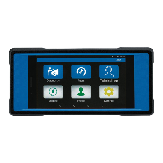
TABLET
12044
These instructions accompanying the product are the original instructions. This document is part of the product,
keep it for the life of the product passing it on to any subsequent holder of the product. Read all these
instructions before assembling, operating or maintaining this product.
This manual has been compiled by Draper Tools describing the purpose for which the product has been
designed, and contains all the necessary information to ensure its correct and safe use. By following all the
general safety instructions contained in this manual, it will ensure both product and operator safety, together
with longer life of the product itself.
AlI photographs and drawings in this manual are supplied by Draper Tools to help illustrate the operation of the
product.
Whilst every effort has been made to ensure the accuracy of information contained in this manual, the Draper
Tools policy of continuous improvement determines the right to make modifications without prior warning.
Advertisement
Table of Contents

Summary of Contents for Draper 12044
- Page 1 AlI photographs and drawings in this manual are supplied by Draper Tools to help illustrate the operation of the product.
-
Page 2: Title Page 1.1 Introduction
Commercial copying, redistribution, hiring or lending is prohibited. No part of this publication may be stored in a retrieval system or transmitted in any other form or means without written permission from Draper Tools Limited. In all cases this copyright notice must remain intact. -
Page 3: Table Of Contents
CONTENTS 1. TITLE PAGE 1.1 INTRODUCTION......................2 1.2 REVISION HISTORY ....................2 1.3 UNDERSTANDING THIS MANUAL ................2 1.4 COPYRIGHT NOTICE ....................2 2. CONTENTS 2.1 CONTENTS ........................3 3. GUARANTEE 3.1 GUARANTEE ....................... 4 4. INTRODUCTION 4.1 SCOPE......................... 5 4.2 SPECIFICATION ...................... -
Page 4: Guarantee
This guarantee applies in lieu of any other guarantee expressed or implied and variations of its terms are not authorised. Your Draper guarantee is not effective unless you can produce upon request a dated receipt or invoice to verify your proof of purchase within the guarantee period. -
Page 5: Introduction
Part No’s........................... FCR-MOT Rated input .......................... 5V Weight ............................ 0.56kg Note: Draper Tools accepts no responsibility for any accident or injury arising from servicing the vehicles system. When interpreting results from the vehicle, always follow the manufacturer’s recommendation for repair. -
Page 6: Health And Safety Information
HEALTH AND SAFETY INFORMATION 5.1 GENERAL SAFETY INSTRUCTIONS For your own safety and the safety of others, and to prevent damage to the equipment and vehicles. The safety messages presented below and throughout this user’s manual are reminders to the operator to exercise extreme care when using this device. Always refer to and follow safety messages and test procedures provided by vehicle manufacturer. -
Page 7: Technical Description
TECHNICAL DESCRIPTION 6.1 IDENTIFICATION Power button. (6) 7 Inch colour touch screen. (2) Volume up/down button. (7) Impact resistant case. (3) Back camera. (8) Front camera. (4) Storage for Vehicle Communications Interface. (9) Speaker. (5) Universal Serial BUS port. - 7 -... -
Page 8: Unpacking And Checking
Lay the contents out and check them against the parts shown below. If any part is damaged or missing; please contact the Draper Helpline (the telephone number appears on the Title page) and do not attempt to use the machine. -
Page 9: Preparation & Connections
PREPARATION & CONNECTIONS 8.1 VEHICLE TO TABLET CONNECTION The system is mainly composed of tablet and VCI connector (14). The following illustration explains how the tablet works with the VCI connector. VCI Connector (Works as the vehicle communication interface Vehicle device for accessing the vehicle data.) To Vehicle's DLC... -
Page 10: Vci Connector
PREPARATION & CONNECTIONS 8.2 VCI CONNECTOR The VCI connector only applies to the passenger vehicles of 12V. It can be installed on the OBDII vehicle's DLC directly or via the extension cable. OBD II 16pin connector (For connecting to vehicle's DLC) Note: Remember to remove the VCI connector from the DLC and re-insert it into the slot on the back... -
Page 11: Register & Update
REGISTER & UPDATE 9.1 REGISTER & UPDATE 1. Launch App-> 2. Create an App Account-> 3. Activate VCI Connector-> 4. Download Diagnostic Software} 1. Launch App: Tap the application icon to Login launch it. Tap "Login" on the right upper corner of the screen. -
Page 12: Connection
10. CONNECTION 10.1. PREPARATION Help DLC Location 1) Switch the ignition on. 2) The vehicle battery voltage should be 9-14V. 3) Throttle should be in a closed position. 10.2 LOCATE VEHICLE'S DLC The DLC (Data Link Connector) provides standard 16 pins and is generally located on driver 's side, about 12 inch away Near centre of dashboard from the centre of dashboard. -
Page 13: Start Diagnostics
11. START DIAGNOSTICS 11.1 START DIAGNOSTICS For new users, follow the sequence below to start a new diagnostic session. Tap "Diagnostic" Select test function Select vehicle model Select test system Select software *Notes: 1. To start diagnosing a vehicle, you have to activate the VCI connector and download the diagnostic software. -
Page 14: Disposal
12. DISPOSAL 12.1 DISPOSAL – At the end of the machine’s working life, or when it can no longer be repaired, ensure that it is disposed of according to national regulations. – Contact your local authority for details of collection schemes in your area. In all circumstances: •... - Page 15 NOTES - 15 -...
- Page 16 ©Published by Draper Tools Limited. No part of this publication may be reproduced, stored in a retrieval system or transmitted in any form or by any means, electronic, mechanical photocopying, recording or otherwise without prior permission in writing from Draper Tools Ltd.
Need help?
Do you have a question about the 12044 and is the answer not in the manual?
Questions and answers