Table of Contents
Advertisement
Quick Links
Advertisement
Table of Contents

Subscribe to Our Youtube Channel
Summary of Contents for Black Diamond Equipment TC1024DCA
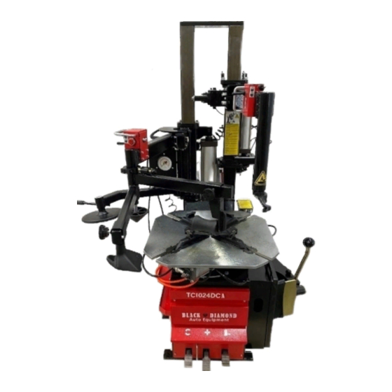
- Page 1 TC1024DCA Tire Changer...
-
Page 2: Table Of Contents
Content IMPORTANT SAFETY INSTRUCTIONS ........3 ● OWNER’S RESPONSIBILITY ............4 ● OPERATOR PROTECTIVE EQUIPMENT ........4 ● NAME OF MAIN PARTS ..............5-6 ● INSTALLATION ..................7-11 ● OPERATION INSTRUCTION ......... 12–16 ● A) Demounting ..........12-14 ● B) Mounting .......... -
Page 3: Important Safety Instructions
(1) IMPORTANT SAFETY INSTRUCTIONS 1. Eye and face protection recommendations: “Protective eye and face equipment is required to be used where there is a reasonable probability of injury that can be prevented by safety glasses, or a face shield must be pro-vided by the owner and worn by the operator of the equipment. -
Page 4: Owner's Responsibility
(2)OWNER’S RESPONSIBILITY 1. To maintain machine and user safety, the responsibility of the owner is to read and follow these instructions: 2. Follow all installation instructions. 3. Carefully check the unit for correct initial function. 4. Read and follow the safety instructions. Keep them readily available for machine operators. 5.Make certain all operators are properly trained know how to safely and correctly operate the unit, and are properly supervised. -
Page 5: Name Of Main Parts
NAME OF MAIN PARTS Bead Break Pedal Clamping Pedal (Open) Clamping Pedal (Close) Rotation Pedal Turntable Mounting Head Swing Arm Dual Assist Arm Control Valve ( Column) Column Assembly Bead Breaker Bead Breaker Pad Lever Inflation Pedal STANDARD ACCESORIES Inflation Gun Lever Lever Protector Mounting Head Pro-... - Page 6 (5) SPECIFICATION Outside clamping 10”~22” 10”~24” Inside clamping 12”~24” 12”~26” Max. wheel width 14” 14” Max. wheel diameter 960mm 1080mm Working air pressure 8~10bar 8~10bar Bead breaker force (at 2500kgf 2500kgf 8bar) Motor speed / 1 speed / 6r.p.m 1 speed / 6r.p.m Operating speed Shipping weight 350kg...
-
Page 7: Installation
(9) INSTALLATION Positioning and installation The machine has been placed in selected positions, marked expansion screws, tighten the mounting ● steadily. All electrical installation must be performed by qualified person. ● Before installation and connection, check if the power voltage of the machine on the nameplate ●... - Page 9 Installation Column 1)Bring the column from other package . 2)Install 8 bolts on the cabinets. ( Bolts was installed on the cabinet) Installation Inflation gun & IT Follow below instruction : 1) Step pedal 2 times and ensure the clamping will be opened.
- Page 10 Installation Swing Arm Install the bolts and nuts according to the picture. This is the air lock swing arm system. Please check the air lock after installation and before operation. Air hose connection should be go through the swing arm to the control valve. Installation Assist Arm Make sure the connection and nuts are well con-...
- Page 11 Installation of assist arm Follow the picture to connect the nut and screw,...
-
Page 12: Operation Instruction
(10) OPERATION INSTRUCTION This unit must be properly operated and properly maintained to help avoid accidents that could injure the operator or bystanders, or damage the unit. This section of the Operating Instructions manual review basic operations and use of controls. These instructions should be reviewed with all employees before they are allowed to work with the machine. - Page 13 7. Move the swing arm into position. Control the valve down on the top of the vertical slide to move the demount head into contact with the rim edge. Push the locking button and lock the slide arm into place (figure 7). Figure 7 - Position Mount/Demount Tool...
- Page 14 H. The tool clearance may change with machine use and 12. Depress the table top pedal to rotate the wheel. The should be inspected often. Failure to maintain the proper Mounting head will guide the tire bead up and over the edge clearance may result in damage to the wheel rim and/or tire.
-
Page 15: B) Mounting
Mounting 1. Before any mounting, inspect tire for damage and verify size match between tire and wheel (fig. 14). This information must be read and followed carefully to prevent accidents and injuries during mounting. Attempts to force a bead seat on mismatched tires and wheels can cause the tire to violently explode, causing seri- ous personal injury or death to operator and/or bystanders. - Page 16 4. Place tire over wheel and move swing arm into position Q. To facilitate the mounting process, you can use the assist making sure the valve stem is at the 9 o’clock position in arm to mount the tire quickly. front of bead lock.
-
Page 17: Inflation
(11) Inflation Tire inflation is performed in three steps: BEAD SEAL, BEAD SEAT, and INFLATION. These steps are explained in detail on page 12. Read the explanation of each step and understand them thoroughly before proceeding. The inflation pedal, located at the rear of the left side of the machine, controls the flow of air through the inflation hose, and has three positions. -
Page 18: Maintenance Tips
Bead Seating Bead seating usually occurs on the long tapered side of the wheel first and the shorter side last. Bead seating will usually require at least 7 PSI in the tire. 40 PSI is the maximum safe pressure at this stage regardless of tire operating pressure. -
Page 19: Diagram
13. Diagram 110V / 220V 380V...
Need help?
Do you have a question about the TC1024DCA and is the answer not in the manual?
Questions and answers