Advertisement
Quick Links
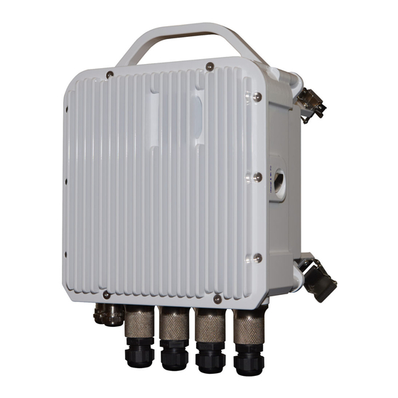
Navigator Radio
Quick Start Guide
NAVIGATOR RADIO TYPES
1
Navigator DT Dual
Transceiver Radio
Navigator ST Single
Transceiver Radio
Available tributary ports may vary depending on the model of Navigator DT or Navigator ST radio.
IDENTIFY PORTS - NAVIGATOR DT
2
IDENTIFY PORTS - NAVIGATOR ST
3
P/N 045-59001-01
11/18
*"Navigator ST First Release" is a single transceiver variant of Navigator DT. This is offered as the
first release of Navigator ST and has the same features as Navigator ST in a slightly larger housing.
NAVIGATOR PHYSICAL PORT TO LOGICAL PORT
4
MAPPINGS
Navigator DT and Navigator ST First
Release
MOUNTING THE RADIO TO THE ANTENNA
5
NOTE. Navigator should be mounted with the Ethernet ports always
facing down.
Attach the Navigator radio, with the radio's Ether-
net connectors facing down, to the antenna using
the four corner clasps of the radio.
CAUTION. We strongly recommend that the technical personnel in-
stalling this radio and ancillaries possess the knowledge and skills ap-
propriate for making such installations.
6
CAUTION. Proper grounding of the outdoor equipment reduces elec-
tromagnetic interference, provides lightning protection, and protects
against electrical discharge. Using improper techniques in lightning-
prone geographic areas may pose a danger to local personnel.
The source and connection points for the building-to-earth ground
near the antenna location should be determined.
CAUTION. IT IS VERY IMPORTANT TO COMPLETE THE GROUND
CABLING PRIOR TO APPLYING ANY DC VOLTAGE TO THE UNIT.
Required method for grounding the radio is to ground the mast to a
ground source. The source and connection points for the building-to-
earth ground in the vicinity of the antenna should be determined.
Also attach an 8 AWG (solid) copper (or equivalent) ground wire to the
m5x.8 grounding stud on the Radio chassis and securely tighten to (15
+/-2in.lbs.) using an 8 mm (5/16 inch) wrench.
Secure the other end of the ground wire to a known earth ground such
as the main ground bar or terminal ground bar of the site. Refer to
local regulations for proper grounding procedures
Navigator ST
Navigator DT ground terminal
CONNECTING GLANDS AND CABLES
7
NOTE. Cable glands are required for external connection of cables to
Navigator.
For the Ethernet cable between Navigator's PoE port and the user's net-
work equipment ensure that the maximum POE cable length between
the ODU and such equipment is 100 m (330 ft.). The maximum POE cable
length between the POE injector and the ODU is 80m (260 ft.).
CAUTION. Any unused port must be sealed with the provided weath-
erproof plugs. Dust plugs delivered pre-installed on the units are not
weatherproof and must be discarded before radio field installation.
GROUNDING
.
Navigator ST ground terminal
Copyright © 2018 REMEC Broadband Wireless Networks (RBWN) LLC. All Rights Reserved.
Advertisement

Summary of Contents for BridgeWave Navigator
- Page 1 +/-2in.lbs.) using an 8 mm (5/16 inch) wrench. *”Navigator ST First Release” is a single transceiver variant of Navigator DT. This is offered as the first release of Navigator ST and has the same features as Navigator ST in a slightly larger housing. ...
- Page 2 4. Attach each wire terminal to the Philips head screws at the sides of the Required Equipment DC connector. Navigator’s DC input is auto polarity and the individual Using the injector back as a drilling template, mark the location of each wires can be attached to either terminal.
- Page 3 CONNECTING AN RJ45 CABLE, LAN OR POE, TO THE CONNECTING A POWER CABLE TO THE POE POE RJ45 PORT CONNECTION TO RADIO Required Equipment From any of Packets 010-59044-0001 to 010-59044-0003, disassemble From any of Packets 010-59044-0001 to 010-59044-0003, disassemble the LAN / PoE connector.
- Page 4 Clicking on the number of directions opens the next window where Measure the RSL at the Navigator radio’s RSL port. The RSL follows a you are offered the choice of editing the configuration or not. typical monotonic response: RSL (dBm) = -10 VBNC ...