Advertisement
(Test chamber for gas sensor evaluation)
Instruction Manual
Table of contents
Thank you very much for purchasing EC01 (Test chamber for gas
sensor evaluation). Please read this instruction manual carefully to use
the product correctly.
EC01
Figaro Engineering Inc.
Instruction Manual
取扱説明書
Page
1
1
2
4
6
8
Advertisement
Table of Contents

Related Manuals for Figaro EC01

Summary of Contents for Figaro EC01
-
Page 1: Table Of Contents
3. Parts names and functions 4. Measurement preparation 5. Measuring procedure 6. Specifications Thank you very much for purchasing EC01 (Test chamber for gas sensor evaluation). Please read this instruction manual carefully to use the product correctly. Figaro Engineering Inc. -
Page 2: Safety Instructions
Instruction Manual 取扱説明書 1. Safety instructions Make sure to follow This test chamber is not explosion-proof. Do not use it for measurements when using flammable gases with greater than 50% concentration of the Lower Explosive Limit (LEL). The test chamber does not guarantee a completely sealed condition. Do not use it for measurements with high concentrations of toxic gases hazardous to the human body. -
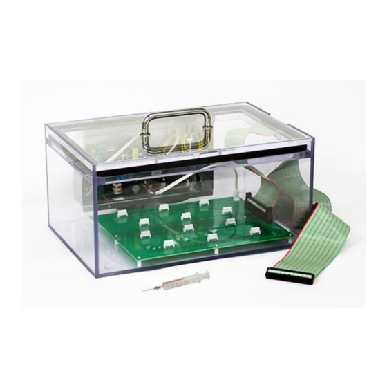
Page 3: Parts Names And Functions
Instruction Manual 取扱説明書 3. Parts names and functions Products and accessories * Make sure that the test chamber for gas sensor evaluation itself and the following accessories are included in the package Instruction Manual Test board for Syringe (5ml) Test chamber for gas (this document) evaluation modules sensor evaluation... - Page 4 Instruction Manual 取扱説明書 Wiring specifications Signal from the test board for evaluation modules (CN1) Evaluation Evaluation Evaluation Evaluation module module module module Connector pin Connector pin number CH number number CH number number number Common 1 to 6 VC (5.0 V DC) CH10 CH11 CH12...
-
Page 5: Measurement Preparation
Instruction Manual 取扱説明書 4. Measurement preparation Prepare a measuring instrument (such as data logger or digital multimeter) that can measure the voltage. ・The measurement device on the right is an example. Wire the voltage measuring instrument. There are two methods for wiring: Connecting a ribbon cable directly to a data logger or other voltage measuring instrument. - Page 6 Instruction Manual 取扱説明書 Attach the sensor to the gas sensor evaluation module, and attach it to the test board for evaluation modules. [Example of attachment of the test board for evaluation modules] Insert the terminal of the gas sensor evaluation module into the larger hole of the connector for the module.
-
Page 7: Measuring Procedure
Instruction Manual 取扱説明書 5. Measuring procedure Close the lid of the test chamber. * The lid should be closed by lightly pressing down to make it airtight. Before injecting the gas, make sure to measure the output voltage from the evaluation module in clean air, and confirm the voltage is stable. - Page 8 Instruction Manual 取扱説明書 How to adjust the power supply voltage The factory setting of the power supply voltage to the test board is set to 5V, and users do not need to adjust it usually. This adjustment should only be made if any adjustment is required between 4.00 V and 5.50 V. The power supply voltage can be adjusted by inserting a + screwdriver into the supply voltage adjustment hole on the side of the control box and turning the adjustment volume.
-
Page 9: Specifications
Lid with air supply and exhaust openings (Model number: EC-P01) (Model number: EC-P02) Contact for inquiries about our products: Figaro USA, Inc. Air inlet and outlet, outer diameter: Board size: 200 x 258 mm 121 S. Wilke Rd. Suite 300 32 mm Φ...
Need help?
Do you have a question about the EC01 and is the answer not in the manual?
Questions and answers