Table of Contents
Advertisement
Quick Links
Introduction:
The x2DRV is a solid state electronic control that will accept a variety of input signals and provides to the brake an output current a
is a solid state electronic control that will accept a variety of input signals and provides to the brake an output current and voltage
is a solid state electronic control that will accept a variety of input signals and provides to the brake an output current a
proportional to the input. This double channel driver can be operated by a remote potentiometer, a voltage or a current loop input.
proportional to the input. This double channel driver can be operated by a remote potentiometer, a voltage or a current
proportional to the input. This double channel driver can be operated by a remote potentiometer, a voltage or a current
The x2DRV is a 24VDC double channel driver, 4Amps current capability.
24VDC double channel driver, 4Amps current capability.
When associated with an xCTRL, power supply, Input and (Communication) will be made by the internal connector.
When associated with an xCTRL, power supply, Input and (Communication) will be made by the internal connector.
When associated with an xCTRL, power supply, Input and (Communication) will be made by the internal connector.
This manual has been designed to cover the full range of installation, start-up and operation of your tension control system.
This manual has been designed to cover the full range of
X2DRV
Tension control system X2DRV
Installation & Operation Manual
Installation & Operation Manual
up and operation of your tension control system.
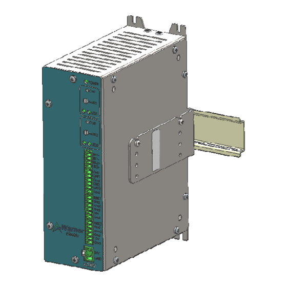
Figure 1:x2DRV housing dimensions
Installation & Operation Manual
29/08/2012
Page 1 of 5
Advertisement
Table of Contents

Related Manuals for Warner Electric X2DRV


Summary of Contents for Warner Electric X2DRV
- Page 1 Introduction: The x2DRV is a solid state electronic control that will accept a variety of input signals and provides to the brake an output current a is a solid state electronic control that will accept a variety of input signals and provides to the brake an output current a is a solid state electronic control that will accept a variety of input signals and provides to the brake an output current and voltage proportional to the input.
- Page 2 Tension control system X2DRV 29/08/2012 Ratings: 24V DC +/- 5% Main Supply Voltage (V) Output 4A with Anti Residual Operating T°C -10°C to 50°C no Condensation Compliance General information: Control chassis should be kept clear of all areas where foreign material, dust, grease, or all might affect the operation of the control.
- Page 3 Figure 3: Power supply wiring Connect wiring from brake magnets to Pin BK1 and/or BK2 of the x2DRV as shown figure 2 Select the Input type with the red switches located along the bottom of the control:...
- Page 4 Tension control system X2DRV 29/08/2012 Wire Controller or PLC (0-10V or 4-20mA Input) to pin InBK1 or InBK2 as shown figure Set the Anti-residual with the white screw as shown figure 4 as describe below: Apply the brake at 0V or 4mA on InBK (1 or 2) or activate the Brake-Off (OFF1 or...
- Page 5 Tension control system X2DRV 29/08/2012 “Teachable Span” calibration procedure Step 1 With the Auxiliary wired to Ana1 (rd) Auxiliary Input Calibration: Ana1 & Ana2 >5s or Ana2 Red LED on Press Cal button >5s. Potentiometer for Anti-residual setting AntiR Step 2...
Need help?
Do you have a question about the X2DRV and is the answer not in the manual?
Questions and answers