Advertisement
Quick Links
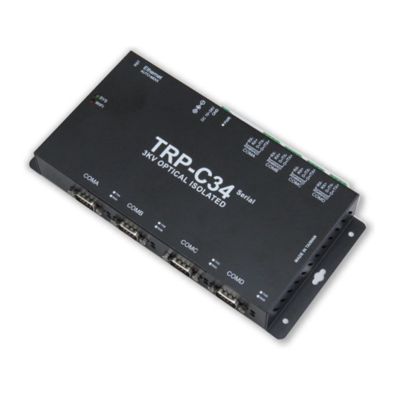
TRP-C34R
User's Manual
4-Port RS232/422/485 Serial Server with 3KV Optical
Isolation
User's Manual
Printed May 2019 Rev 1.0
Trycom Technology Co.,Ltd
No.35, Zhongxing Rd., Guishan Township, Taoyuan County 333, Taiwan.
Tel : 886-3-350-3351 Fax: 886-3-350-3352
Web: www.trycom.com.tw
Copyright
Copyright Notice: The information in this manual is subject to change without notice to improve reliability, design and
function and does not represent a commitment on the part manufacturer. No part of this manual may be reproduced,
copied, or transmitted in any form, without prior written permission by the manufacturer. Products mentioned in this
manual are mentioned for identification purposes only. In this manual, product names appearing may or may not be
registered trademarks of their respective companies or copyright.
Advertisement

Summary of Contents for Trycom Technology TRP-C34R
- Page 1 User’s Manual 4-Port RS232/422/485 Serial Server with 3KV Optical Isolation User’s Manual Printed May 2019 Rev 1.0 Trycom Technology Co.,Ltd No.35, Zhongxing Rd., Guishan Township, Taoyuan County 333, Taiwan. Tel : 886-3-350-3351 Fax: 886-3-350-3352 Web: www.trycom.com.tw Copyright Copyright Notice: The information in this manual is subject to change without notice to improve reliability, design and function and does not represent a commitment on the part manufacturer.
- Page 2 Systems WIN 32bit XP /Vista/2003Server/2008 Server (32-bit & 64-bit), 2000 Server OS, Win 7 (32-bit & 64-bit), WIN 8(32/64 bit),The driver establishes a transparent connection between host and serial device by mapping the IP: Port Number of the TRP-C34R’s Serial Port to a local COM Port on the host computer.
- Page 3 RS485 data without lost, Specify hardware can ensure on line RS485 device working fine. The TRP-C34R has four synchronous D SUB 9 pin serial port for RS232 connection and 4 screw terminal block for RS422/485 and power connection. The Ethernet port support Auto-MDIX and Auto-select 10/100MB.
-
Page 4: Hardware Description
2. Hardware Description The following information is provided to give the user an understanding of how to connect the TRP-C34R to the LAN and serial device. A review of the switch settings and the functionality of the LED’s are also provided. - Page 5 2-4. RST button Keeping pushes the RST button over 10-sec when power on, and the SYS and WiFi LEDs will blinking then TRP-C34R will be back to factory default setting. 3. Install TRP-C34R Hardware STEP1: Please connect the power source, the PWR LED will on and wait the SYS LED will...
- Page 6 STEP2: Connect TRP-C34R with internet port by RJ45 LAN cable. *The TRP-C34R Support Auto-MDIX, A straight-through or crossover Ethernet cable can be used to make a connection directly to the HUB/Router/PC. STEP3: Connect TRP-C34R with serial device. 3-1. RS485 Wiring 3-2.
- Page 7 4. How to configure TRP-C34R There are 2 ways to access the Server Properties and program the TRP-C34R. a. Using the IoT Device Finder utility. b. Using the WEB Server...
- Page 8 D: Save, reboot and back factory settings. 4-2. Searching LAN for TRP-C34R Once TRP-C34R is connected to the LAN the IoT Device Finder utility will search it and display it in a window by name, IP address, Mac….Information, please click the “Find” button to looking for that.
- Page 9 4-3.Configuring Server Properties Click the GoTo button, when the login prompt appears, login using the administrator and password. Click Log In. the factory default setting below: User Name: admin Password: admin...
- Page 10 Please click the “Log In” button after you completed the User Name and Password. 4-4.System web UI: Admin Password: Maximum 25 chars. Confirm Password: Input the password again. Auto Reset (Minutes): Sets the amount of time a user can remain idle before being reset. Device Name: Device server name.
- Page 11 4-5.Network web UI: Wireless: Option, it should be disabled. Ethernet: Static Mode: Selecting Static IP requires the user to assign the IP information for the device manually. *Please make sure your host pc the network segment as same as this IP. Such as: PC:192.168.1.xx, and the device is 192.168.1.100.
- Page 12 4-6.Serial web UI: From Serial1,Serial2,Serial3 to Serial4. Baud Rate: From 300,600,2400,4800,9600,19200,38400,57600,115200,230400,460800 and 921600 bps. Parity:None,Even,Odd. Data Bits:5,6,7,8 Stop Bits:1,2 Flow Control:None,XON/XOFF. RxDelay(ms):0 TxDelay(ms):0 4-7.Serial Over TCP/IP 4 Ports:...
- Page 13 From Serial 1 Over TCP, Serial 2 Over TCP, Serial 3 Over TCP and Serial 4 Over TCP. There are 4 modes for selection: TCP Server, TCP Client, UDP, and DISABLED.
- Page 14 TCP server. Configure TCP server port number and message time out period, TRP-C34R will wait for client connection in this mode. b. TCP Client. Allow configuring 4 remote destination host IP address, port number. TRP-C34R establishes a connection with the remote host and sending data to the remote host actively in this mode.
- Page 15 5. Application Multi-Function Application 5-1 Direct IP Mod Example: Step1: Connect PC-----Ethernet-----TRP-C34R-----RS485---TRP-C28 (RS485 ID=01) Step2.Run TRPCOM utility and input IP/Port, click “Link” button, then Send Command , The Response will appear TRP-C28 I/O Status.
- Page 16 PC to one serial server; Support Ethernet and Internet , If TRP-C37 off line or power fail, The Virtual-Com utility will try to Reconnection. Step 1. Insert the TRP-Serial CD and find the TRP-C34R folder. Step 2.Click “Vcomm.exe” icon then install Virtual-COM utility.
- Page 17 Step3. Click “OK” button and select “VSP run as Client support Server Device”. Step4. Select “Create virtual serial by device scanner”, then press “OK” Step5. Run VCOMM.exe then click right button select “New Virtual COM” Step6. Select “Select Serial Port” and input TRP-C34R IP and port then press “OK”.
- Page 18 Step7. If Virtual-Com setting success, the display will appear bellow. Step8. Run TRPCOM utility then select virtual-com port make a TRP-C34R loop test.
- Page 19 *If in VCOMM‘s configuration select “Boot with windows”, the virtual-com will Auto-connection when windows start. 5-2 Virtual COM Mode...
- Page 20 Example: Step1. Connect PC-----Ethernet------TRP-C34R-----RS485---TRP-C28 (RS485 ID=01). Step2. Run Virtual-COM utility and make a virtual-COM port, Run TRPCOM utility and input com port number, press “OK”. Step3.Select “Terminal” and send command, the response will appear TRP-C28 channel 2 counter value.
- Page 21 The TRP-C34R is able to analyze Modbus protocols and auto to convert between Modbus TCP and Modbus RTU/ASCII. As Serial Modbus master (PLC) to Modbus TCP slave. The TRP-C34R is able to analyze the protocol from Serial Master then send them to every Modbus TCP slave devices.
Need help?
Do you have a question about the TRP-C34R and is the answer not in the manual?
Questions and answers