
Related Manuals for Simrad Simrad ES18


Summary of Contents for Simrad Simrad ES18
- Page 1 Installation Manual Simrad ES18 Split-beam transducer TECHNOLOGY FOR SUSTAINABLE FISHERIES www.simrad.com...
-
Page 3: Table Of Contents
The purpose of this manual is to provide the information, procedures and basic drawings required for the physical installation of the Simrad ES18. The manual further provides relevant descriptions and illustrations to explain the basic principles for location and noise considerations. - Page 4 If you require maintenance or repair, contact your local dealer. You can also contact us using the following address: simrad.support@simrad.com. If you need information about our other products, visit https: //www.simrad.com. On this website you will also find a list of our dealers and distributors. Kongsberg Maritime AS www.kongsberg.com...
- Page 5 Installation Manual Table of contents ABOUT THIS MANUAL .............. 5 INTRODUCTION............... 7 Simrad ES18 ........................8 Proposals for the collection of multifrequency acoustic data ..........8 Order information ......................9 Physical and environmental specifications ..............10 Support information ......................11 TRANSDUCER HANDLING AND MAINTENANCE....... 13 Rules for transducer handling ..................14...
- Page 6 Simrad ES18 Installing the transducer using a hull unit ................58 Using a suitable inclination angle ..................59 Using self-locking taps ....................59 WHERE TO INSTALL THE TRANSDUCER ......... 63 Introduction to transducer location ..................64 Mount the transducer deep....................64 Avoid protruding objects near the transducer ..............65 Mount the transducer at forward part of hull to minimize the effects from the flow boundary water layer....................66...
-
Page 7: Note
About this manual About this manual The purpose of this manual is to present the descriptions and drawings required to install the Simrad ES18 Split-beam transducer. Target audience The manual is intended for technical personnel; such as skilled shipyard workers, electricians, qualified engineers and naval architects. - Page 8 Simrad ES18 Installation Manual Registered trademarks Observe the registered trademarks that apply. Windows ® is a registered trademark of Microsoft Corporation in the United States and other countries. Simrad ® , SIMRAD ® and the Simrad ® logo are either registered trademarks, or trademarks of Kongsberg Maritime AS in Norway and other countries.
-
Page 9: Introduction
Introduction Introduction Topics Simrad ES18, page 8 Proposals for the collection of multifrequency acoustic data, page 8 Order information, page 9 Physical and environmental specifications, page 10 Support information, page 11 404770/B... -
Page 10: Simrad Es18
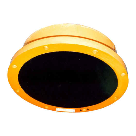
Simrad ES18 Installation Manual Simrad ES18 The Simrad ES18 is a split-beam transducer designed for fish finding and underwater science applications. The beamwidth is 11 degrees at nominal operational frequency 18 kHz. The transducer uses 44 "tonpilz" elements organized in four separate sectors. -
Page 11: Order Information
Introduction Korneliussen, R. J., Diner, N., Ona, E., Berger, L., and Fernandes, P. G. 2008. Proposals for the collection of multifrequency acoustic data. – ICES Journal of Marine Science, 65: 982–994. You may find this paper both interesting and useful in relation to the installation and use of the ES18. -
Page 12: Physical And Environmental Specifications
Simrad ES18 Installation Manual Related topics Introduction, page 7 Physical and environmental specifications These physical and environmental specifications are important for handling, storage and installation. Note We are continuously working to improve the quality and performance of our products. The technical specifications may be changed without prior notice. -
Page 13: Support Information
Introduction Support information If you need technical support for your Simrad ES18 you must contact your local dealer, or one of our support departments. A list of all our offices and dealers is provided on our website. You can also contact our main support office in Norway. - Page 14 Simrad ES18 Installation Manual Canada • : Kongsberg Mesotech Ltd. Company name • : 1598 Kebet Way, Port Coquitlam, BC, V3C 5M5, Canada Address • : +1 604 464 8144 Telephone • : +1 604 941 5423 Telefax • https://www.simrad.com Website •...
-
Page 15: Transducer Handling And Maintenance
Transducer handling and maintenance Transducer handling and maintenance Topics Rules for transducer handling, page 14 Approved anti-fouling paints, page 15 Inspecting and cleaning the transducer face, page 17 Painting the transducer face, page 18 404770/B... -
Page 16: Rules For Transducer Handling
Simrad ES18 Installation Manual Rules for transducer handling To secure long life and accurate results, the transducer must be handled correctly. A transducer must always be handled as a delicate instrument. Incorrect actions may damage the transducer beyond repair. Observe these transducer handling rules: Do not activate the transducer when it is out of the water. -
Page 17: Approved Anti-Fouling Paints
Approved anti-fouling paints Because some paint types may be aggressive to the polyurethane in the transducer, consult our list of approved paints. The list can also be found on http://www.simrad.com. Observe the relevant instructions and safety information provided by the paint manufacturer. - Page 18 – : Intergard 269 Primer Apply 40 µm dry film thickness. – : Intersmooth 7465Si SPC Paint Apply 100 µm dry film thickness. The list can also be found on http://www.simrad.com. Related topics Transducer handling and maintenance, page 13 404770/B...
-
Page 19: Inspecting And Cleaning The Transducer Face
Transducer handling and maintenance Inspecting and cleaning the transducer face Marine growth (biological fouling) on the transducer face reduces the ES18 performance. For this reason, it is important to keep the transducer face clean. Every time your vessel is in dry dock, you must remove the marine growth. At the same time, you must inspect the transducer closely for physical damage. -
Page 20: Painting The Transducer Face
Check for dents, scratches, holes or other damage to the surface. If you find suspicious damage, take high resolution photos that show the damage. Contact your dealer or the Simrad support organization for advice. If necessary, apply anti-fouling paint as described in the dedicated procedure. - Page 21 Transducer handling and maintenance • Airless spray Because some paint types may be aggressive to the polyurethane in the transducer, consult our list of approved paints. Context The transducer has not been designed with any protection against biological fouling. Anti-fouling paint may therefore be applied to the transducer face. To minimize the negative acoustical effects the layer of anti-fouling paint must be as thin as possible.
- Page 22 Simrad ES18 Installation Manual Further requirements The contractor or shipyard must keep a daily paint log recording all relevant information from the surface treatment. Related topics Transducer handling and maintenance, page 13 Approved anti-fouling paints, page 15 Installing the transducer, page 21...
-
Page 23: Installing The Transducer
Installing the transducer Installing the transducer Topics Installation summary, page 22 Designing, manufacturing and mounting the installation hardware, page 23 Installing the cable gland, page 25 Designing, manufacturing and mounting the steel conduit, page 27 Unpacking the transducer from its transport crate, page 29 Installing the transducer cable, page 30 Mounting the transducer, page 33 Painting the transducer face, page 34... -
Page 24: Installation Summary
Simrad ES18 Installation Manual Installation summary The installation of the ES18 transducer is a key task for successful installation of the echo sounder system. Not only will you need to penetrate the vessel’s hull, you must also to select a physical location for maximum performance and minimum acoustic and electric noise. -
Page 25: Designing, Manufacturing And Mounting The Installation Hardware
Installing the transducer Based on the shape of the transducer housing, and the mounting devices available, determine the installation method. Design, manufacture and mount the necessary fairing, installation blister, keel box and/or tank that is required to mount the transducer. Install the bushing. - Page 26 Simrad ES18 Installation Manual • The installation method has been determined. • The cable gland has been installed. • All relevant personnel (naval architects, designers, skilled shipyard workers) and tools must be available. Context The installation shipyard must provide all necessary installation drawings. If required, all drawings and documents provided by shipyard for the installation of the transducermust be approved by the vessel’s national registry and corresponding maritime authority...
-
Page 27: Installing The Cable Gland
Installing the transducer Installing the cable gland In order to secure the vessel’s watertight integrity, it is extremely important that the transducer cable penetrates the ship’s hull in a safe manner. One suggested method is to use a cable gland. The cable gland consists of a bushing, rubber gasket, washers and a packing nipple. - Page 28 Simrad ES18 Installation Manual Further requirements Before you can put the transducer cable through the cable gland, the steel conduit must be installed. Related topics Installing the transducer, page 21 404770/B...
-
Page 29: Designing, Manufacturing And Mounting The Steel Conduit
Installing the transducer Designing, manufacturing and mounting the steel conduit A steel conduit is used to protect the transducer cable. The conduit serves two purposes. It will protect the cable, and shield it from electric noise. Depending on how the steel conduit is terminated over the transducer, it may also secure the watertight integrity of the vessel. - Page 30 Simrad ES18 Installation Manual approved by the vessel’s national registry and corresponding maritime authority and/or classification society. Such approval must be obtained before the installation can begin. The shipowner and shipyard doing the installation are responsible for obtaining and paying for such approval.
-
Page 31: Unpacking The Transducer From Its Transport Crate
Installing the transducer Unpacking the transducer from its transport crate The ES18 transducer is shipped in a wooden box. Prior to installation, the transducer must be unpacked from its box, and placed under the mounting location. Prerequisites You must be equipped with a standard set of tools. This tool set must comprise the normal tools for mechanical tasks. -
Page 32: Installing The Transducer Cable
Simrad ES18 Installation Manual Open the shipping box. Note Be careful! Do not use heavy tools. Do not use excessive force. Make sure that you do not damage the transducer or the cable. Lift the transducer straight up and out of the box. - Page 33 Installing the transducer Context The transducer cable is attached to the transducer, and it has a fixed length. The bushing and the associated parts are included in the delivery. Note All necessary precautions must be made to avoid damage to the cable while pulling it through the steel conduit.
- Page 34 Simrad ES18 Installation Manual Continue until you reach the transceiver.Allow the transducer cable to form a service loop close to the transducer. Note Be careful! Make sure that you do not damage the outer surface of the transducer cable. If water leaks into a cable, it may damage the transducer beyond repair.
-
Page 35: Mounting The Transducer
Installing the transducer Mounting the transducer When all the preparations have been made, the transducer is mounted. If required, additional and more detailed procedures must be provided by the installation ship yard. Prerequisites The following requirements must be met before mounting the transducer: •... -
Page 36: Painting The Transducer Face
Simrad ES18 Installation Manual Context Observe the physical size and weight of the transducer. Unless a suitable lifting device is available, make sure that enough manpower is available to lift, hold and fasten the transducer. Procedure Lift the transducer up into its location. Align the holes on the mounting flange with the holes in the mounting ring. - Page 37 Installing the transducer • Primer • Anti-fouling paint • Wet film gauge • Airless spray Because some paint types may be aggressive to the polyurethane in the transducer, consult our list of approved paints. Context The transducer has not been designed with any protection against biological fouling. Anti-fouling paint may therefore be applied to the transducer face.
- Page 38 Simrad ES18 Installation Manual Allow the paint to dry. Further requirements The contractor or shipyard must keep a daily paint log recording all relevant information from the surface treatment. Related topics Transducer handling and maintenance, page 13 Approved anti-fouling paints, page 15...
-
Page 39: Cable Layout And Interconnections
Cable layout and interconnections Cable layout and interconnections Topics Connecting the transducer cable to the transceiver, page 38 ES18 Connecting to a 12-pin Amphenol socket, page 39 12-pin Amphenol plug , page 42 Connecting the transducer to the other transceivers, page 43 Splicing the transducer cable, page 44 404770/B... -
Page 40: Connecting The Transducer Cable To The Transceiver
Simrad ES18 Installation Manual Connecting the transducer cable to the transceiver Once the transducer cable has been installed, you can connect it to the transceiver using the plug provided. Prerequisites Electrical connections can only be made by skilled personnel (ship electricians, technicians or engineers). -
Page 41: Es18 Connecting To A 12-Pin Amphenol Socket
ES18 Connecting to a 12-pin Amphenol socket The Simrad ES18 is a split-beam transducer designed for fish finding and underwater science applications. The transducer is connected to terminals A through N on a circular 12-pin Amphenol socket (Type 97-12-19S). This socket is used on the General Purpose Transceiver (GPT), and on several versions of the Wide Band Transceiver (WBT). - Page 42 Simrad ES18 Installation Manual Cable with colour coded conductors Cable with colour coded conductors Sector Cable colours Terminal on socket Transceiver channel White Black Green Black Yellow Black Blue Black Digital output Digital ground Black Cable screen Screen Cable with only black and white conductors The cable has four pairs of white and black conductors.
- Page 43 Cable layout and interconnections Connecting to the Amphenol socket The cable screen must be connected to the housing on the transducer plug. Note The black wires in the transducer cable are not for grounding. You must never connect these together. You must never connect any of them to vessel ground.
-
Page 44: 12-Pin Amphenol Plug
Simrad ES18 Installation Manual 12-pin Amphenol plug The transducer socket on the transceiver allows you to connect one or more single or split beam transducers using a 12-pin Amphenol plug (97-24-19P). In order to connect the transducer cable to the plug, the plug must be disassembled as described below. -
Page 45: Connecting The Transducer To The Other Transceivers
Cable layout and interconnections Connecting the transducer to the other transceivers The ES18 transducer can be connected to several different echo sounder transceivers. It is not practical to include all types of plugs and transceivers in this manual. Use the cable information provided for the 12-pin Amphenol plug, and connect the transducer as specified in the relevant echo sounder manual. -
Page 46: Splicing The Transducer Cable
Simrad ES18 Installation Manual Splicing the transducer cable If you need to extend the transducer cable, you must splice it correctly. This is very important, as any splice is very vulnerable for noise. Cable can be spliced using two different methods: •... -
Page 47: Splicing The Cable Using A Grounded Junction Box
Cable layout and interconnections Splicing the cable using a grounded junction box Do not solder the wires together using only electrical tape for insulation. This will result in electrical noise and reduced operational performance. Junction box Cable gland Terminal block Cable Cable screen (Do not connect the cable screen to vessel... -
Page 48: Splicing The Cable Using A Junction Box Isolated From Vessel's Ground
Simrad ES18 Installation Manual Splicing the cable using a junction box isolated from vessel’s ground Do not solder the wires together using only electrical tape for insulation. This will result in electrical noise and reduced operational performance. Do not connect the cable screen to vessel ground. -
Page 49: Transducer Installation Principles
Transducer installation principles Transducer installation principles Topics Transducer installation in a blister, page 48 Transducer installation in keel box, page 51 Transducer installation in a flush mounted steel tank, page 52 Transducer installation using an arctic tank with acoustic window, page 53 Transducer installation inside the hull, page 55 Transducer installation using drop keel, page 56 Installing the transducer using a hull unit, page 58... -
Page 50: Transducer Installation In A Blister
Simrad ES18 Installation Manual Transducer installation in a blister In order to install a transducer with a circular housing, one recommended installation method is by means of a blister. The blister must be designed and manufactured by the installation shipyard to fit the transducer, as well as the vessel’s size and hull shape. - Page 51 Transducer installation principles Example Streamlined blister Stiffening rib Drainage holes Inclination angle Mounting ring Air outlet Cable service loop Bushing Height: 400 mm (Minimum) Rounded corners Physical location of the blister The blister is placed on the side of the hull. The distance from the keel is a trade off between a close distance giving a turbulent flow of water in a narrow passage, and a large distance bringing the transducer higher up, and therefore more affected by the vessel roll.
- Page 52 Simrad ES18 Installation Manual Keel Transducer blister Horizontal distance between the keel and the blister Vertical distance between the bottom of the keel and the blister surface Observe the horizontal and vertical distances between the keel and the transducer blister. (C + D)
-
Page 53: Transducer Installation In Keel Box
End user manuals and source drawings (normally in AutoCad format) can be downloaded from our website. • https://www.simrad.com Smooth surface is important Make sure that the surface of the transducer face, as well as the plating and putty around the transducer is as even and smooth as possible.Obstructions on these surfaces will... -
Page 54: Transducer Installation In A Flush Mounted Steel Tank
Simrad ES18 Installation Manual Mounting screws or bolts must not be extruding from the transducer or the plating immediately around it. Note Obstructions on these surfaces will create problems with turbulent flow, and may cause noise. Related topics Transducer installation principles, page 47... -
Page 55: Transducer Installation Using An Arctic Tank With Acoustic Window
End user manuals and source drawings (normally in AutoCad format) can be downloaded from our website. • https://www.simrad.com Smooth surface is important Make sure that the surface of the transducer face, as well as the plating and putty around the transducer is as even and smooth as possible.Obstructions on these surfaces will... - Page 56 Simrad ES18 Installation Manual Example Steel tank Acoustic window Cable service loop Bushing Cable in steel conduit Oil inlet Using the mounting ring This large circular is transducer is designed to be mounted using the integrated flange and a mounting ring.The mounting ring is welded to the hole prepared for the transducer.
-
Page 57: Transducer Installation Inside The Hull
Transducer installation principles Transducer installation inside the hull The transducer can be mounted inside the hull. This installation method forces the transducer to send and receive the acoustic pulses through the hull plating. This requires a good acoustic contact between the transducer face and the hull. In order to install the transducer like this, you must design and build a tank around the transducer. -
Page 58: Transducer Installation Using Drop Keel
Simrad ES18 Installation Manual Note Make sure that the "Forward" direction on transducer points in the forward direction of the vessel. A suitable mounting ring can be provided by Kongsberg Maritime. A drawing is available for local manufacturing. End user manuals and source drawings (normally in AutoCad format) can be downloaded from our website. - Page 59 End user manuals and source drawings (normally in AutoCad format) can be downloaded from our website. • https://www.simrad.com Smooth surface is important Make sure that the surface of the transducer face, as well as the plating and putty around the transducer is as even and smooth as possible.Obstructions on these surfaces will...
-
Page 60: Installing The Transducer Using A Hull Unit
ES18 transducer below the boundary layer. Note Several Simrad sonars are provided with hull units of various sizes. Any one of these hull units can be redesigned for use with a ES18 transducer. If this is a realistic option, call your dealer or Kongsberg Maritime for advice. -
Page 61: Using A Suitable Inclination Angle
Transducer installation principles Using a suitable inclination angle Ideally, the transducer face should be mounted in parallel with the sea surface when the vessel is in normal trim, as this will provide the most accurate echo information. However, it is also very important that the water flow over the transducer face is laminar. In order to ensure laminar flow, the transducer face must be tilted slightly upwards in relation to the water flow. - Page 62 Simrad ES18 Installation Manual Emuge’s saw-tooth profile up to pitch P ≤ 0.7 mm Emuge’s saw-tooth profile up to pitch P >0.7 mm Standard thread External thread Internal thread The advantages of using Emuge self-lock thread include: • The thread locking feature if integrated in the internal thread •...
- Page 63 Transducer installation principles Drawing standard Whenever self-locking threads are required, this is shown on the technical drawing. In the case of tapping through holes, the arrow at the end of the center line illustrates the screw-in direction of the bolt. The drawing is normally provided with the following - or similar - text: Drill diameters for threads differ from standard.
- Page 64 Simrad ES18 Installation Manual Self-lock taps provided by Kongsberg Maritime Several self-lock taps are on stock at Kongsberg Maritime, and can be ordered from us. Threads Part number Drill diameter for threads ø5.2 mm 700–078838 ø7.0 mm 700–078531 ø8.8 mm 700–078408...
-
Page 65: Where To Install The Transducer
Where to install the transducer Where to install the transducer Topics Introduction to transducer location, page 64 Mount the transducer deep, page 64 Avoid protruding objects near the transducer, page 65 Mount the transducer at forward part of hull to minimize the effects from the flow boundary water layer, page 66 Keep the transducer far away from the propellers, page 67 Mount the transducer at a safe distance from bow thruster(s), page 67... -
Page 66: Introduction To Transducer Location
Simrad ES18 Installation Manual Introduction to transducer location A single answer to the question "where to install the transducer" cannot be given. The physical location of the transducer depends on the vessel's design and construction, how the hull is shaped, and how the water runs along the hull. There are however a number of important guidelines, and some of these are even conflicting. -
Page 67: Avoid Protruding Objects Near The Transducer
Where to install the transducer Slamming Slamming happens if the vessel hull climbs out of the water in heavy seas. The force of the water when the hull falls down may push the transducer up, and may cause damage both to the transducer and to its mounting. This is especially important for low frequency transducers with large faces. -
Page 68: Mount The Transducer At Forward Part Of Hull To Minimize The Effects From The Flow Boundary Water Layer
Simrad ES18 Installation Manual Mount the transducer at forward part of hull to minimize the effects from the flow boundary water layer The upper water layers of the sea contain a myriad of small air bubbles created by the breaking waves. When the hull moves through water it will cause a disturbance, and this will generate friction. -
Page 69: Keep The Transducer Far Away From The Propellers
Where to install the transducer Keep the transducer far away from the propellers The propulsion propellers is the dominant noise source on most vessels. The noise is easily transmitted through the water. This noise may often reduce the overall performance of your ES18. The transducer must be installed as far away from the propellers as possible. -
Page 70: Summary And General Recommendations
Simrad ES18 Installation Manual Summary and general recommendations Some of the installation guidelines provided for transducer location may be conflicting. For this reason, each vessel must be treated individually in order to find the best compromise. In general, the most important factor is to avoid air bubbles in front of the transducer face. - Page 71 Where to install the transducer If the vessel hull has a bulbous bow, this may well be a good transducer location, but also in this case the flow pattern of the aerated water must be taken into consideration. The foremost part of the bulb is often a good location. Thruster Transducer location This applies to the vessel in normal trim and speed.
-
Page 72: Drawing File
Simrad ES18 Installation Manual Drawing file Topics About the drawings in the drawing file, page 71 107783 Dimensions ES18, page 72 088815 Mounting arrangement ES18, page 74 088814 Mounting ring ES18, page 77 088759 Mounting procedure ES18, page 79 404770/B... -
Page 73: About The Drawings In The Drawing File
DWG format. The original drawings can be downloaded from our website. https://www.simrad.com Some drawings and documents are not available from our website. These can be downloaded from the Simrad Dealer Club. https://www.simrad.com/sdc The installation shipyard must provide all necessary design and installation drawings, as well as the relevant work standards and mounting procedures. -
Page 74: 107783 Dimensions Es18
Simrad ES18 Installation Manual 107783 Dimensions ES18 Download the source drawing from the transducer pages on https://www.simrad.com. 404770/B... - Page 75 Drawing file Related topics Drawing file, page 70 404770/B...
-
Page 76: 088815 Mounting Arrangement Es18
Simrad ES18 Installation Manual 088815 Mounting arrangement ES18 Download the source drawing from the transducer pages on https://www.simrad.com. 404770/B... - Page 77 Drawing file 404770/B...
- Page 78 Simrad ES18 Installation Manual Related topics Drawing file, page 70 404770/B...
-
Page 79: 088814 Mounting Ring Es18
Drawing file 088814 Mounting ring ES18 Download the source drawing from the transducer pages on https://www.simrad.com. 404770/B... - Page 80 Simrad ES18 Installation Manual Related topics Drawing file, page 70 404770/B...
-
Page 81: 088759 Mounting Procedure Es18
Drawing file 088759 Mounting procedure ES18 Download the source drawing from the transducer pages on https://www.simrad.com. 404770/B... - Page 82 Simrad ES18 Installation Manual Related topics Drawing file, page 70 404770/B...
- Page 83 Index Index 12-pin Amphenol plug target audience ..........5 assembly and wiring........42 bow thrusters acoustic noise..........67 transducer installation ........67 box keel transducer installation ........51 about bushing acoustic window ......... 53 transducer cable .......... 25 arctic tank ..........53 bow thruster noise ........
- Page 84 Simrad ES18 Installation Manual mounting ring ......50–51, 53–55, 57 protruding objects........65 propellers..........67 hull unit retractable transducer........58 transducer installation ........58 transducer blister......... 48 hydrophone transducer in drop keel ........56 anti-fouling paints ........15 transducer inside hull........55 dimensions about ............
- Page 85 25 transducer connection ........43 self locking taps outline dimensions mounting ring ..........59 about ............71 Simrad ES18 ............72 support ............ 11 physical and environmental specifications ... 10 size overview ES18 ............72 transducer installation ........22 ES18 mounting ring drawing......
- Page 86 Simrad ES18 Installation Manual this manual purpose ..........1, 5 washer target audience ..........5 transducer cables......... 25 transceiver weight connecting the transducer cable....38–39 physical and environmental specifications ... 10 transducer plug assembly and wiring ....42 wiring transducer transducer cable ..........
- Page 88 ©2020 Kongsberg Maritime...
Need help?
Do you have a question about the Simrad ES18 and is the answer not in the manual?
Questions and answers