
Related Manuals for RDS Technology Loadmaster 8000i


Summary of Contents for RDS Technology Loadmaster 8000i
- Page 1 Loadmaster 8000i On-Board Weighing System Operation RDS Part No.: S/DC/500-10-565 Document Issue: 1.20 : 17/1/08 Software Issue: PS 312-001 rev. 09...
- Page 2 44 (0) 1453 733311 for further information. Our policy is one of continuous improvement and the information in this document is subject to change without notice. Check that the software reference matches that displayed by the instrument. © Copyright RDS Technology Ltd 2008 \UK565120.DOC...
-
Page 3: Table Of Contents
CONTENTS OVERVIEW Introduction ............................... 5 System Technical Details ..........................5 Calibration ................................. 5 Weighing Units ..............................5 Loading Attachments ............................5 The Head Unit ..............................6 Menu keys ................................. 6 Data Entry................................6 STARTUP _____________________________________________________________ 7 Switch On ................................7 Zero Prompt .............................. - Page 4 CONTENTS CUSTOMER AND PRODUCT STORES ___________________________________ 14 Modes of use..............................14 Store Setup ............................... 14 4.1.1 Enable/Disable the Stores facility (Customer Mode) ................. 14 4.1.2 Enabling the "Reference" facility......................15 4.1.3 Selecting Batch Mode / Blend Mode ....................15 4.1.4 Setting a Preset Load (Customer Mode only)..................
-
Page 5: Overview
1 - OVERVIEW Introduction The LoadMaster 8000i weighing system is installed mainly on Front End Loaders. Two pressure sensors are mounted on each of the hydraulic lift system. They provide an increase of frequency signal as the load increases. The average frequency is captured at a set weighing point provided by the Reference/Direction sensor assembly. -
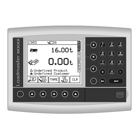
Page 6: The Head Unit
1 - OVERVIEW The Head Unit Figure 2 “Target load” “Return to MAIN Screen” Numeric Keypad This is the load in tonnes Used to enter a 'Target Press at any time to return from the Tare screen or any other you want to load on the Load'. -
Page 7: Startup
2 - STARTUP Startup Before you start to load you need to check a few things, Work the hydraulics to get up to normal operating temperature. • Set Zero Weight • Set the Target load. • Set Preset Tare (if required) •... -
Page 8: Static Zero (Static Weighing Mode)
2 - STARTUP Figure 8 Figure 9 symbol denotes that this is a zero done during normal operation. NOTE: If the "live last bucket" is used, the dynamic zero will be followed by the static zero (as described below). 2.3.2 Static Zero (Static Weighing Mode) Pressing the key displays the "Static Zero"... -
Page 9: Set Target Load
2 - STARTUP Set Target Load This is the weight you want to load on the vehicle (fig. 13). From the MAIN screen, simply key-in the target weight and then press the ENTER key to confirm. As you commence the loading cycle, the figure will decrease to show how much is left to load. -
Page 10: Set The Load Enter Mode
2 - STARTUP Set the Load Enter mode The Load Enter mode should normally be set to . The load will be automatically entered as the bucket is lifted above the weighing position. Alternatively, if you prefer to manually enter the bucket weight on every lift, then hold the SUB MENU key to select Set Product Density (Volumetric weighing only) If you are weighing in cubic metres (m... -
Page 11: Weighing
3 - WEIGHING Weighing The system also has several compensatory features allowing for varying lift speed, weighing 'on the move', and (if an optional angle sensor is fitted) weighing on a slope, to maintain accuracy. Even with these features however, smooth lifting with the loader stationary will always ensure the best results. -
Page 12: Static Weighing
3 - WEIGHING Static Weighing This normally uses the loader's auto-kickout system to automatically stop the lift arms in the reference position, before sampling the weight. The weighing screen (fig. 19) will appear the same as for dynamic weighing mode. Fill the bucket as normal and crowd it right back. -
Page 13: Clear Last Entry
3 - WEIGHING Clear Last Entry If the last bucket weight was entered in error, then press the to delete it. NOTE: When using the instrument in the ‘Blend Mode’ (section 4.9), each bucket weight is added straightaway to the Product, Batch, Grand Total and 7-day Stores straight away, as opposed to when the CLR button is pressed. -
Page 14: Customer And Product Stores
4 – CUSTOMER AND PRODUCT STORES Customer and Product Stores There is a "pool" of 1000 individual memory stores available. Of these, up to 500 can be programmed as Customer Stores ( ). The remaining stores in the "pool" are available as Product Stores ( ) allocated to each Customer Store. -
Page 15: Enabling The "Reference" Facility
4 – CUSTOMER AND PRODUCT STORES 4.1.2 Enabling the "Reference" facility In the Customer store mode you can enter up to three ancillary references (e.g. vehicle number, customer order reference etc.). Each time you select a customer / product store, only Reference 1 ( ) will appear on the MAIN screen. -
Page 16: Programming A Store Description
4 – CUSTOMER AND PRODUCT STORES 4.1.5 Programming a Store Description From the SETUP screen, press "2. Stores Data", to display the STORE SETUP screen (fig. 24). Select either "1. Product" or "2. Customer" and press ENTER to display the PRODUCT SETUP or CUSTOMER SETUP screen (fig. 29). Position the cursor under the first letter of the "Product"... -
Page 17: Connecting A Printer
4 – CUSTOMER AND PRODUCT STORES Connecting a Printer The top port is factory set for connecting an RDS ICP printer, without further configuration being necessary. If another printer is used (or you want to select an option other than a printer), you can configure the settings from the ‘SETUP’... -
Page 18: Reset All Stores (All Modes)
4 – CUSTOMER AND PRODUCT STORES Figure 32 Figure 33 Product Summary (Customer Customer Summary Mode) 4.4.1 Reset All Stores (All Modes) NOTE: Be absolutely sure that any customer / product information you wish to keep a record of, has in fact been saved, either on printouts or onto a Data Card ! Press the STOR key twice. -
Page 19: View / Print The 7-Day Total (All Modes)
4 – CUSTOMER AND PRODUCT STORES 4.5.2 View / Print the 7-day Total (All Modes) Press the key (fig 35) to view the daily totals of the last seven days. Press PRNT to print the 7-day total summary (fig. 37). Figure 37 Selecting the Printer Output Mode By default, the print mode is OFF. -
Page 20: Programming A Batch Via The Instrument
4 – CUSTOMER AND PRODUCT STORES 4.8.1 Programming a Batch via the instrument Using the RDS Upload/Download kit, You can upload batch data (section 4.1.6), however, without this optional equipment, programming batch data is done manually on the instrument as follows; From the STORE SETUP page with the "2 Batch (program)"... -
Page 21: Print The Last Batch Load / All Batch Loads
4 – CUSTOMER AND PRODUCT STORES Load in the normal way in order to meet the target weight. When you have loaded the desired weight for that product, press the CLR key. The bucket weight display will zero and the target weight is set for the next product in the batch. -
Page 22: Batch (Blend) Mode
Load 2000 Load Management System® software from “CC Software Ltd”. The Loadmaster 8000i can be configured to either simply transmit load information as each load is completed, or have bi-directional communication, receiving order information for designated vehicles from the PC. -
Page 23: System Settings
5 – SYSTEM SETTINGS System Settings A number of settings can be programmed by the operator from the SETUP menu. These settings are accessible without a PIN number. NOTE: Certain menus including the 'Calibration', 'Printer Setup' and 'Weighing Units' menus are not accessible to the operator. Adjusting Screen Contrast or Brightness From the SETUP screen, press;... -
Page 24: Set Instrument Id
5 – SYSTEM SETTINGS Set Instrument ID From the SETUP screen, press; 3. System Settings *. More 1. Instrument ID You can reprogramme up to 2 lines of 20 characters, using the alpha- numeric keypad. The first line is the information that will appear at the bottom of the roll summary. -
Page 25: Weighing Units
5 – SYSTEM SETTINGS Weighing Units From the SETUP screen, press; 3. System Settings 4. Weighing Units Choose units of either kg, lbs, UK tons, US tons, Metric tonnes, cubic metres or cubic yards. For lbs or kg units you can also set the resolution i.e. displaying to the nearest 1, 5, 10, 20, 25, 50 or 100 lbs or kgs. -
Page 26: Document History
NOTES Document History Issue 1: 18/7/07 Document revised from UK181-8.DOC Issue 1.01 13/11/07 Document revised ref. section 4.1.6 Issue 1.02 19/11/07 Minor revisions Issue 1.03 29/11/07 Correction ref. p.8 Issue 1.04 9/12/07 Addition to figure 2 Issue 1.2 17/1/08 Correction ref. section 4.3...
Need help?
Do you have a question about the Loadmaster 8000i and is the answer not in the manual?
Questions and answers