Table of Contents
Advertisement
Quick Links
1 0 0 D a v i d s D r i v e
H a u p p a u g e , N e w Y o r k 1 1 7 8 8 - 2 0 3 4
T e l : 6 3 1 4 3 6 7 4 0 0
F a x : 6 3 1 4 3 6 7 4 3 1
www. m i t e q . c o m
TECHNICAL NOTE 25T065
DECEMBER 2006
REV E
NSU REDUNDANT SWITCHOVER SYSTEM
____________________________________
SECTION 1
INTRODUCTION
1.1 GENERAL DESCRIPTION
1.1.1 PHYSICAL
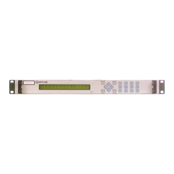
Figure 1-1. Front Panel, Control Unit
Figure 1-2. Rear Panel, NSUN Control Unit
Figure 1-3. Rear Panel, NSU2 Control Unit
Figure 1-4. Rear Panel, NSU1-R Control Unit
1
Advertisement
Table of Contents

Summary of Contents for Miteq NSU
- Page 1 F a x : 6 3 1 4 3 6 7 4 3 1 www. m i t e q . c o m TECHNICAL NOTE 25T065 DECEMBER 2006 REV E NSU REDUNDANT SWITCHOVER SYSTEM ____________________________________ SECTION 1 INTRODUCTION 1.1 GENERAL DESCRIPTION 1.1.1 PHYSICAL...
- Page 2 Figure 1-5. Internal View, NSU2 Control Unit 1.1.2 FUNCTIONAL The MITEQ 1:N New Switchover Unit (NSU) is designed to provide improved reliability for advanced satellite communications systems. The NSU consists of a Control Unit, Switch Modules and frequency converters. The Control Unit monitors the status of up to twelve primary frequency converters and one backup frequency converter.
- Page 3 In the event of a power supply failure the Control Unit can remain fully operational while the power supply is replaced. To reduce operating costs the NSU may be placed in an unoccupied facility and be totally controlled and monitored from a remote system controller. All front panel controls and indications are available to a host monitor and control system.
- Page 4 Option 17C: RS232 Remote Interface Figure 1-6. Rear Panel, Switch Module (For Use With NSUN) 1.2 EQUIPMENT CHARACTERISTICS 1.2.1 PHYSICAL NSU Control Unit Weight ......................12 pounds nominal Chassis Dimensions................. 19” x 20” x 1.75” panel height Converter Control and Status connectors ................DE-9S .........................DB-25S(NSU1-R ONLY)
-
Page 5: Connector Wiring Information
Designation Ground Data + +24V ‘A’ +24V ‘A’ Return Data- +24V ‘B’ +24V ‘B’ Return Table 1-2. NSU Remote Interface Connections Control Unit Remote Interface and Status Connector (J16) 9-Pin D-Subminiature RS485 and RS422 RS232 Designation Designation Ground RCV Data... - Page 6 Primary Converter and the NSU will enable the Primary Converter settings to be stored automatically in the NSU. In the absence of a Serial Link between the Primary Converter and the NSU, the Primary Converter settings must be manually stored in the NSU.
- Page 7 ADJUST 5/10 MHZ IF MON +4 +/-3dBm NOTE: FOR 9800/9900 SERIES CONVERTERS EQUIPPED WITH ETHERNET OPTION 17H CONNECT J7 INSTEAD OF J6 OF THE CONVERTER TO THE NSU. Figure 1-7. NSU1-S50 RF Connections to Converter PRIMARY 01 BACKUP IF BACKUP...
- Page 8 ADJUST 5/10 MHZ IF MON +4 +/-3dBm NOTE: FOR 9800/9900 SERIES CONVERTERS EQUIPPED WITH ETHERNET OPTION 17H CONNECT J7 INSTEAD OF J6 OF THE CONVERTER TO THE NSU. Figure 1-9. NSU1-B50/B50, NSU1-B75/B75 or NSU1-S50/S50 RF Connections PRIMARY 02 PRIMARY 01...
- Page 9 +4 +/-3dBm PRIMARY 02 Rx/Tx NOTE: FOR 9800/9900 SERIES CONVERTERS EQUIPPED WITH ETHERNET OPTION 17H CONNECT J7 INSTEAD OF J6 OF THE CONVERTER TO THE NSU. Figure 1-11. NSU2-B75 or NSU2-B50 RF Connections to Converter PRIMARY 01 PRIMARY 02 BACKUP IF...
- Page 10 Switch Module for switching polarization. The NSU1 and NSU2 are fixed configurations and cannot be expanded nor can they support polarization switching. NSU System The NSU1 is a 1:1 configuration with the switch modules integrated into a 1 rack unit with the control unit.
- Page 11 9800 Series converters have been designed to physically accommodate the Switch Module. Control Unit The Control Unit is responsible for the monitor and control of the NSU System. Primary Unit A Primary Unit is a component that is in the signal path of communications traffic. The NSUN can accommodate up to twelve Primary Units.
- Page 12 An Active Fault indicates the NSU is presently experiencing a failure that is impeding ideal operation of the NSU. An active fault will cause the “STATUS” button on the front panel to light red and the status contacts will indicate a fault. The Event Log will contain information about the fault condition and the time and date that the fault occurred.
-
Page 13: Redundancy Operation
NSU-Converter Serial Link should be disabled for that chain position. If the Backup NSU-Serial Link is disabled, a fault in a Primary converter will cause the transfer switches to switch but none of the settings of the Backup Converter will be changed. - Page 14 • The Backup Unit is switched to standby. • The NSU Control Unit screen switches to the Redundancy Chain Status display. • If a Primary Unit fails, it is switched into standby and the Backup Unit is switched online in place of the failed Primary Unit (as long as there are no higher priority units already in standby).
- Page 15 Begin Place all Primary Units into Auto Mode. Switch Backup Unit into Standby position and Check converter status via converter bus. Any Primary Unit fault? Backup Unit fault? Any unit fault with greater priority than unit in standby? Backup Unit fault? Switch faulty converter with highest priority to standby.
- Page 16 SECTION 2 INSTALLATION 2.1 UNPACKING, STORAGE, RESHIPMENT Carefully open the shipping container and remove the equipment. Inspect the equipment thoroughly and report any damage. If the equipment is to be stored, it should be wrapped in plastic and kept in a clean, dry place.
-
Page 17: Turn-On Procedure
Switch Modules for redundancy operation. Connect J14 to the first (J14, J15 NSUN Only) Switch Module and J15 to the last Switch Module. NSU Monitor and This is an optional connection allowing the operator to monitor and Control Connector control the equipment from a remote location. This connector also... - Page 18 NSU polling, the NSU will retain the last known operational parameters and continue to protect the converter. If a switch module for a given path stops responding to NSU polling or the switch indicates a fault, a fault will be reported in the NSU. The NSU will continue to operate.
- Page 19 Press the “AUTO” indicator button it should light green to indicate Auto mode and the Primary converters should be Online and the Backup should be in Standby. • Press the “AUTO” indicator button again. It should no longer be lit indicating the NSU is now in Manual mode. •...
- Page 20 • Press the “AUTO” indicator button it should light green to indicate Auto mode and the Primary converters should be Online and the Backup should be in Standby. • The system is now armed and operational.
-
Page 21: Operation
See Figure 1-1 for the physical layout of the front panel. The LCD backlight is lit when power is on. The “STATUS” indicator button will light red to indicate an active fault in the NSU System. The “STATUS” indicator button will light amber when there are no active faults but there is fault activity stored in the log that have not been cleared (either remotely or from the front panel). -
Page 22: Keypad Operation
The NSU will always power up in Remote control mode. If the NSU is left in the local control mode, after a thirty-minute period of no front panel keypad activity the NSU will switch back into Remote control mode. -
Page 23: Data Entry
The lower row of the display shows the transfer switch position and status of the individual Switch Modules. The individual settings and NSU- Converter Serial Link options of each converter can be accessed from this screen. - Page 24 Blinking characters in the lower row for a particular chain position indicate the NSU is either unable to communicate with the switch module in that redundancy chain position or the switch module is indicating a fault.
- Page 25 ↑BK 01 ↓ST ON The display above shows the Redundancy Chain status screen for an NSU1 system. This system can only back up one primary converter. ↑BK 01 02 ↓ST ON ON The display above shows the Redundancy Chain status screen for an NSU2 system. This system can back up two Primary converters.
- Page 26 Redundancy Chain Status screen. The polling process updates the settings stored in the NSU for converters that have their NSU-Converter Serial Link option enabled. The operator must enter settings stored in the NSU for converters that have NSU-Converter Serial Link disabled.
- Page 27 Use the up and down arrow keys or the numeric entry keys to enter the desired Priority. • Press “ENTER” to save the Priority in the NSU. If the priority is set a value greater than 12, an error tone is generated and the entry will be revoked.
- Page 28 The slope setting of the Primary Converter has no bearing on the NSU operations and cannot be accessed from this screen. For example, when the backup converter is online...
- Page 29 When the polarization of the converter in Standby is changed, the Polarization Switch is set to the new polarization. NSU-Converter Serial Link Subscreen The NSU-Converter serial link for each chain position can be enabled or disabled from a subscreen of the Converter Settings Subscreen. →01 NSU-CONVERTER SERIAL LINK:ENABLED...
-
Page 30: Status Screen
For convenience, pressing the “STATUS” indicator button can immediately access the Status Screen. This screen provides access to the status of the NSU. This screen also allows the operator to review and clear the event log. The event log records the time and date of significant events including all fault activity. - Page 31 Redundancy Priority changes • Redundancy Chain Configuration change (add or remove positions) • Transfer Switch Position (Online/Standby) changes • Polarization Switch Position (Horizontal/Vertical) changes • NSU Control Mode changes (Remote/Local) → EVENT 1 OF 32 JUNE 3 2004 19:53:01 Startup...
- Page 32 Clear Event Log To clear the Event Log of its contents: • Press the left or right arrow key to highlight the Clear Log field on the display. • Press the “ENTER” key. A message will appear: “PRESS ENT TO CLEAR THE EVENT LOG.” •...
- Page 33 RS485/RS422/RS232 Parameters Standard units are equipped with an RS485/RS422 interface. To operate in a 2-wire configuration RS485 should be selected. To operate in a 4-wire configuration RS422 should be selected. For units equipped with the RS232 option this field cannot be changed.
-
Page 34: Static Ip Address
This screen gives the operator the option to defer the reset until all Ethernet parameters have been updated. Select “YES” and Press “ENTER” to re-start the NSU. Select “NO” and press “ENTER” to dismiss the screen and enter other Ethernet parameters. -
Page 35: Dynamic Ip Address
Use the ↑↓ arrow keys to choose between Dynamic IP Address and Static IP Address. Press “ENTER”. • The RESET screen shown above will appear. Choose “YES” and the NSU will reset with a dynamically assigned IP address. ↑ DYNAMIC IP ADDRESS: 192.168.001.001... - Page 36 To Change the Ethernet Password: • Press the right arrow key to select the Ethernet Password field on the display. • Use the up or down arrow keys to choose between an Ethernet Password or disabling the Ethernet Password. • Use the numeric entry keys to enter a five-digit Ethernet Password.
-
Page 37: System Information Screen
MODEL NSUN 2-S50/S50 ↓ FIRMWARE 160061 V1.00 160222 V1.00 This screen displays the model numbers and firmware versions of the NSU Control Unit and connected Switch Modules. To view the information of a single element of the Redundancy Chain: •... -
Page 38: Remote Operations
SECTION 4 REMOTE OPERATIONS The equipment is supplied with an RS485/RS422 bus interface and an Ethernet interface. As an option the unit can be supplied with RS232 instead of the RS485/RS422 interface. 4.1 SERIAL REMOTE PROTOCOL (RS485/RS422/RS232) The command structures for the serial buses; RS485, RS422 and RS232 are identical. All transmissions are multi-byte sequences beginning with a header byte and ending with a trailer byte and checksum byte. -
Page 39: Command Code Summary
+ 32); 4.2 COMMAND CODE SUMMARY The following paragraphs describe each of the command codes. The NSU will also respond to the legacy command set used in the RSUN, 1-N Broadband Redundant Switching Unit. Please refer to MITEQ Technical Note 25T030 for more information on... -
Page 40: Command Codes
ACS command requires all 26 parameters. For an NSU1 and NSU2 if a change to a serial link or chain position outside the range of the NSU is attempted the NSU will respond with “b”: illegal parameter or parameter out of range. The acceptable range for... - Page 41 * = no change to stored value in position The QUERY command requires no parameters. The query form of this command informs the operator of the operational condition of each NSU-Converter Serial Link and the status of the converter contacts in the redundancy chain.
- Page 42 Note: Once a chain position has been de-activated the converter contacts must be removed and the reconnected for the NSU to detect the presence of a converter again. A chain position cannot be created using any form of the $ACS command.
- Page 43 The following is an example of querying Active Converter Status for an NSU2 with a Backup and two Primary converters connected. Query Cmd: ?ACS Reply: ?ACS000----------C000---------- The reply shows that there are two Primary converters and a Backup converter all with serial links enabled and no contact errors.
- Page 44 It will be updated even if the attenuation value is the same as what is presently stored in the Primary converter. If the serial link between the NSU Control unit and a Primary converter is disabled, a Backup converter with a serial link will still be able to replace that failing Primary converter at the correct output levels by using the attenuation and Gain Equalization data stored in the NSU Control unit.
- Page 45 Second, 2-digit ASCII numeric characters 4.2.7 SET ALL ETHERNET PARMETERS = EAD The SET command requires three 12-digit parameters indicating the Ethernet IP address, Ethernet gateway and the Ethernet subnet mask of the NSU control unit. Remote Command Sequence: $EADIiiiiiiiiiiiiGggggggggggggSssssssssssss Unit Response: $EAD...
- Page 46 The QUERY command requires no parameters. Remote Command Sequence: ?EAD Unit Response: ?EADIiiiiiiiiiiiiGggggggggggggSssssssssssss EAD: Ethernet Address indicator. If the indicator is capitalized in the remote response, then the IP address that was set is a Static IP address. If the indicator is in lower case letters then the IP address is a Dynamic IP address and was obtained using DHCP (Dynamic Host Configuration Protocol) server to assign the IP address.
- Page 47 4.2.9 UNIT FREQUENCY = FRQ The SET command requires two parameters. One parameter is two digits in length representing the redundancy chain position, and the other parameter is twelve digits in length representing RF frequency in Hz. Leading zeros must be used. Refer to Section 4 for an explanation of converter settings operation.
- Page 48 4.2.11 EVENT LOG = LOG The only SET command clears the unit log of its contents. Remote Command Sequence: $LOG00 Response: $LOG The QUERY command requires a two-digit parameter indicating the log entry to be examined. If entry 00 is queried, the unit returns the number of log entries currently in the log, otherwise the unit responds with the date, time and a code indicating the event which has occurred.
- Page 49 Event Indicator Event 0 Event Log Cleared 1 Unit startup 2 Power Supply ‘A’ Fault 3 Power Supply ‘A’ Fault Recovery 4 Power Supply ‘B’ Fault 5 Power Supply ‘B’ Fault Recovery 6 Non-volatile memory fault 7 Redundancy Mode Changed to AUTO 8 Redundancy Mode Changed to MANUAL 9 Control Mode Changed to REMOTE 10 Control Mode Changed to LOCAL...
- Page 50 Event Indicator Event 69 Primary Converter 6 Both Contacts Open Fault Recovery 70 Primary Converter 7 Both Contacts Open Fault 71 Primary Converter 7 Both Contacts Open Fault Recovery 72 Primary Converter 8 Both Contacts Open Fault 73 Primary Converter 8 Both Contacts Open Fault Recovery 74 Primary Converter 9 Both Contacts Open Fault 75 Primary Converter 9 Both Contacts Open Fault Recovery 76 Primary Converter 10 Both Contacts Open Fault...
- Page 51 Event Indicator Event 120 Primary Converter 6 Serial Link Fault 121 Primary Converter 6 Serial Link Fault Recovery 122 Primary Converter 7 Serial Link Fault 123 Primary Converter 7 Serial Link Fault Recovery 124 Primary Converter 8 Serial Link Fault 125 Primary Converter 8 Serial Link Fault Recovery 126 Primary Converter 9 Serial Link Fault 127 Primary Converter 9 Serial Link Fault Recovery...
- Page 52 Event Indicator Event 171 Switch 5 Fault Recovery 172 Switch 6 Fault 173 Switch 6 Fault Recovery 174 Switch 7 Fault 175 Switch 7 Fault Recovery 176 Switch 8 Fault 177 Switch 8 Fault Recovery 178 Switch 9 Fault 179 Switch 9 Fault Recovery 180 Switch 10 Fault 181 Switch 10 Fault Recovery 182 Switch 11 Fault...
- Page 53 4.2.12 UNIT MODEL = MNB There is no SET command. The QUERY command requires no parameters. Remote Command Sequence: ?MNB Response: ?MNBnnnnnnnnnnnnnnnnnnnnnnnnnnnnnn nnnnnnnnnnnnnnnnnnnnnnnnnnnnnn: Up to Thirty-character model name. 4.2.13 UNIT MODEL NUMBER = MOD There is no SET command. The QUERY command requires no parameters. Remote Command Sequence: ?MOD Response: ?MODmm mm: ASCII string character representing model number...
- Page 54 4.2.14 UNIT NAME = NAM The SET command requires an ASCII string from one to twenty digits in length indicating the name of the unit. Allowable characters are in the range of 20H to 7AH. Remote Command Sequence: $NAMnnnnnnnnnnnnnnnnnnnn Response: $NAM The QUERY command requires no parameters.
- Page 55 Remote Command Sequence: ?PRInn Response: ?PRInnPpp PRI: Redundancy chain priority indicator. nn: Two-digit ASCII numeric characters “01” to “12” indicating chain position P: Priority indicator. pp: Two-digit ASCII numeric characters indicating priority, “01” through “12”, “01” is the most critical. 4.2.17 UNIT REDUNDANCY MODE = RED The SET command requires a one-digit parameter indicating the redundancy mode selection Manual or Automatic.
- Page 56 SLP: Slope command indicator nn: Two digit ASCII numeric characters, Indicating primary converter. “01” through “12”. S: Slope parameter indicator s: ‘+’ or ‘-‘ indicating sign. gg: Two-digit parameter indicating slope in 0.2 dB steps. If the response returns ?SLPnnS???, this indicates that the backup path does not have slope capability. 4.2.20 UNIT STATUS = STA There is no SET command.
- Page 57 Remote Command Sequence: $SWPpp Unit Response: $SWP SWP: Switch Position indicator. pp: Two digit ASCII numeric characters, MSD transmitted first, LSD last. Indicating the position that will be switched into standby “00” through “12”, valid Redundancy Chain positions “00” is the backup chain position and is used to set all other switches back to their online positions.
- Page 58 The QUERY command requires one parameter, a two-digit parameter that indicates either the NSU control unit or a transfer switch module. Remote Command Sequence: ?VER(nn) Response: ?VERDddddddVv.vvvDddddddVv.vvv ?VERnnDddddddVv.vvv.vvv When nn is omitted the version data returned is for the NSU Control unit...
- Page 59 The Pass-Through command allows either SET or QUERY commands to be passed through the NSU Control unit directly to the converter connected to a given position in the Redundancy Chain. For the NSU control unit to communicate with a converter in the Redundancy Chain the NSU- Converter Serial Link for that converter must be enabled.
-
Page 60: Ethernet Interface
ASCII printable characters. The address is 41H (ASCII code 'A') for these examples. Return the number of entries stored in the event log of the NSU. The NSU returns a response that indicates that there are 3 entries in the event log. - Page 61 Gateway (NSU example setting 0.0.0.0) The computer must be configured with the same Subnet Mask as the NSU, but a different IP address, to connect properly. For connecting with the NSU unit address in the example above, the following settings are recommended for the PC: IP Address (Corresponding PC setting 192.168.1.2)
- Page 62 NSU, this application can re-assign the IP address of the NSU unit. For an example the NSU is connected to a PC through a crossover cable. The IP address of the PC is 192.168.001.002. The address of the NSU will be set to 192.168.001.001.
- Page 63 Figue 4-1. IPSETUP Application 4.3.6 VERIFYING PROPER CONNECTION AND CONFIGURATION The connection and configuration may be verified from a PC attached to the LAN using the network “ping” command. From a command prompt, enter “ping <assigned IP address>” The response will indicate whether a connection was established. 4.4 ACCESSING THE SYSTEM THROUGH THE ETHERNET CONNECTION 4.4.1 ACCESS VIA THE WEB INTERFACE All system setting may be may be queried or modified via the Web Interface.
- Page 64 Trap Destination View or set the SNMP Trap destination address Time Page Function Name Description Set Clock View or set the system real-time clock functions of the NSU Miscellaneous Page Function Name Description Enable Telnet Permit or prevent Telnet access...
-
Page 65: Access Via Telnet
MITEQ. 1. Make sure that the NSU is in the Remote control mode 2. Access the web page for the NSU. Note the IP Address and password of the NSU unit. 3. Go to the Misc Settings page and make sure that Enable Reflash is checked. - Page 66 10. If the NSU password has not been disabled, a “Password needed box will appear. For the user name type NSU. Enter the password that you use to login to the web page. 11. A progress screen will appear. When complete a message box that reports if the process completed successfully or not.
- Page 67 Appendix A – Reaching the Unit by NAME Instead of IP Address If the NSU is connected to a LAN equipped with a Domain Name Server, the network manager may be able to configure the server to associate a particular text name with an IP address.
- Page 68 Glossary 10-baseT Controlled-impedance cable used for Ethernet wiring Crossover Cable An Ethernet cable wired with the signal pairs reversed, to permit connection of two computer devices. Direct Cable An Ethernet cable wired with the signal pairs directly connected, to permit connection between a computer and hub or router File Transfer Protocol, a protocol for moving files between computers via a TCP/IP connection...
Need help?
Do you have a question about the NSU and is the answer not in the manual?
Questions and answers