
Summary of Contents for AA4C AA-2PFP45
- Page 1 Version: Serial No.: Production Date: USER’S MANUAL ELECTRO-HYDRAULIC TWO-POST LIFT AA-2PFP45 AA4C AUTOMOTIVE CO.,LTD...
-
Page 2: Table Of Contents
USER’S MANUAL TABLE OF CONTENTS Chapter 1 DESCRIPTION OF THE MACHINE ........................1 1.1 FIXED STRUCTURE ................................1 1.2 MOVING UNITS ..................................1 1.3 LIFTING UNITS ..................................2 1.4 HYDRAULIC POWER UNIT ..............................2 1.5 CONTROL BOX ..................................2 1.6 SAFETY DEVICES ................................. - Page 3 USER’S MANUAL 4.4 ASSEMBLING ..................................12 4.5 TESTING AND CHECKS TO PERFORM BEFORE START-UP ..................14 4.6 SEP UP ....................................15 Chapter 5 OPERATIONS AND USE ............................16 5.1 COMMANDS…………………………………………………………………………………………………………16 5.2 OPERATING SEQUENCE ..............................16 Chapter 6 MAINTENANCE ..............................6.1 PRECAUTIONS ..................................
-
Page 4: Chapter 1 Description Of The Machine
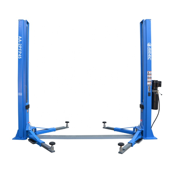
USER’S MANUAL Chapter 1 DESCRIPTION OF THE MACHINE The electro-hydraulic 2-post lift is a fixed installation. This means that it is anchored to the ground and built for lifting and positioning automobiles and vans at a certain height off the ground. The lift consists of the following main parts: ◆... -
Page 5: Hydraulic Power Unit
USER’S MANUAL ◆ ◆ Arms locking system; 1 hydraulic unit (Fig. 2-7), on the command side, to set the cylinders run. ◆ 4 foot guards on the arms; 1.4 HYDRAULIC POWER UNIT ◆ A synchronous device to control the carriages The hydraulic power unit consists of: movement;... -
Page 6: Chapter 2 Technical Specifications
(see Chapter 4 INSTALLATION-ELECTRIC PLANT CONNECTION) 2.3 HYDRAULIC UNIT PUMP MOTOR Fig. 4 Type Model Model No. AA-2PFP45 7.8cm 6.0cm Size Capacity 10000lbs Transmission: coupling type Overall Height 2822mm... -
Page 7: Hydraulic Oil Hose Connection Diagram
USER’S MANUAL 2.6 HYDRAULIC OIL HOSE CONNECTION DIAGRAM Fig. 7 DESCRIPTION Fig. 5 1Ph Electrical Diagram Lock valve Operating Cylinder with simple effect Manual lowering valve Check valve Motor Pump Filter Pressure relief valve Flow control valve Tank Table 5 2.7 VEHICLE WEIGHT AND SIZE Lift rack can be adapted to virtually all vehicles no heavier than 4000kg, the dimensions of which do not exceed the... -
Page 8: Maximun Dimensions Of Vehicles To Be Lifted
USER’S MANUAL Always keep the capacity of the lift in mind in the case of Chapter 3 SAFETY vehicles with particular characteristics. It is vital to read this chapter of the manual carefully and THE SAFETY area will be determined by the dimensions from beginning to end as it contains important information of the vehicle. -
Page 9: General Precautions
USER’S MANUAL 3.3 RISKS AND PROTECTION DEVICE We shall now examine the risks to which the operator and the maintenance fitters may be exposed when the vehicle is immobilized in the raised position, together with the protection devices and adopted by the manufacture to reduce all such hazards to the minimum. -
Page 10: Risks While The Vehicle Is Being Raised
USER’S MANUAL WARNING ◆ The maximum pressure valve (Fig. 13), located on the hydraulic oil power unit, will trip if the lift is DO NOT ATTEMPT TO MOVE THE VEHICLE WHEN overloaded. IT IS RESTING ON THE DISK SUPPORT PLATES. It is important to position the vehicle on the lift so that the weight is correctly distributed on the arms. -
Page 11: Risks Of Persons
USER’S MANUAL structure. During this phase, the operator must remain in ◆ If the hydraulic cylinder breaks, the safety wedges the command zone. (Fig. 17) will trip (Fig. 16), located inside the posts. The wedges are pushed by the spring and immediately stop the carriage preventing their descent. - Page 12 USER’S MANUAL Fig. 22 Fig. 19 NEVER LEAN OBJECTS AGAINST THE POSTS OR LEAVE THEM IN THE AREA WHERE MOVING 3.6.4 RISK DUE TO VEHICLE MOVEMENT PARTS ARE LOWERED. Movement may be caused during operations, which This could hamper lowering or cause the vehicle to fall involve force sufficient to move the vehicle.
-
Page 13: Safety Instructions For Servicing
USER’S MANUAL ALWAYS KEEP THE AREA SURROUNDING AND THE LIFT CLEAN BY REMOVING ALL OIL SPILLS. To avoid the risk of slipping, make use of the recommended personal protection (anti-slip footwear). 3.6.7 RISK OF ELECTRIC SHOCK Risk of electric shock in areas of the lift housing electric wiring. -
Page 14: Chapter 4 Installation
USER’S MANUAL Chapter 4 INSTALLATION FOLLOWING OPERATIONS MUST PERFORMED EXCLUSIVELY BY SPECIALISED TECHNICAL STAFF WITH AUTHORISATION FROM THE MANUFACTURER OR LICENSED DEALER. IF THESE OPREATIONS ARE PERFORMED BY OTHER PERSONS, SERIOUS PERSONAL INJURY AND/OR IRREPERABL DAMAGE TO THE LIFT UNIT MAY RESULT. -
Page 15: Floor
USER’S MANUAL 4.3 FLOOR The lift must be installed on a horizontal concrete bed a minimum thickness of 200mm built and a resistance ≥30N/mm The floor must also be flat and level (10mm of tolerance for leveling). Consult the manufacturer with regard special applications. - Page 16 USER’S MANUAL 4.4.3 ELECTRIC PLANT CONNECTION ◆ Screw the joint of the high-pressure hose and fix it on the base. WARNING 4.4.2 HYDRAULIC PALNT The operations listed below must be performed by skilled personnel. ◆ Install the pump on the hock board according to Fig. 32 and fix it on the bottom of main column.
-
Page 17: Testing And Checks To Perform Before Start-Up
USER’S MANUAL ◆ Block the spring ring at the end of the pin. WARNING End-user should confirm that the over load device must be connected before the electrical power connected to lift. 4.4.5 INSTALL THE COVER PLATE Install the cover plates at the chassis by 4 pieces M8× 16 bolts. -
Page 18: Sep Up
USER’S MANUAL 4.6.2 LOAD TESTS ◆ Cylinder operation Repeat the previous tests with the vehicle on the rack. NOTE: If oil is not present, fill the reservoir of the power unit with the necessary amount of oil .See the procedure After the load tests, visually inspect the machinery and in Chapter 6: MAINTENANCE check again that all bolts are tightened. -
Page 19: Chapter 5 Operations And Use
USER’S MANUAL Chapter 5 OPERATIONS AND USE 5.2.2 PARKING Once the required height has been reached, keep pressing The lift Commands (control devices) is shown as Fig. 38. the lowering lever on the power pack. The movement is stopped automatically when the safety wedge rests on the level of the first slot that they come in contact with while the carriages are coming down. -
Page 20: Chapter 6 Maintenance
USER’S MANUAL Chapter 6 MAINTENANCE ◆ Complete functional diagram electric equipment and auxiliary equipment indicating the 6.1 PRECAUTIONS power supply connections; WARNING ◆ Hydraulic diagram with lists of parts and max. pressure values; Maintenance must be carried out ONLY BY SKILLED PERSONNEL WHO ARE VERY FAMILIAR WITH ◆... - Page 21 USER’S MANUAL type of oil, see Page 3 “TECHNICAL SYNCHRONOUS CABLE SPECIFICATIONS”. Check the pulleys and pulley races conditions. Control the cable wear by checking diameter, possible broken wires, ◆ After the first 40 hours of operation, check if the other damages or relevant changes.
-
Page 22: Periodic Lubrication Chart
USER’S MANUAL warehouse for an extended period of time. Oil should be Chapter 7 TROUBLESHOOTING disposed as indicated in Appendix A, Page 21. 7.1 TROUBLESHOOTING GUIDE AFTER EACH MAINTENANCE OPERATION, THE MACHINE MUST RETURN INITIAL Troubleshooting and possible repairs require absolute CONDITIONS, INCLUDING THE DISASSEMBLEED compliance with ALL THE SAFETY PRECAUTIONS PROTECTION AND SAFETY DEVICE. - Page 23 USER’S MANUAL Problem Possible Cause Solution Burnt fuse The lift does non rise when the Line current does not arrive Replace fuse pushbutton is pressed Malfunction in the electric plant: Connect again (motor does not run) -Broken limit switch Call Service Center -burnt motor Top un oil level Not enough oil...
-
Page 24: Appendix A Special Notes
USER’S MANUAL APPENDIX A SPECIAL NOTES A.1 DISPOSAL OF USED OIL Used oil, which is removed from the power unit and the plant during an oil change, must be treated as a polluting product, in accordance with the legal prescriptions of the country in which the lift is installed. -
Page 25: Appendix B Spare Parts
USER’S MANUAL APPENDIX B SPARE PARTS B.1 SPARE PARTS When replacing parts and making repairs, comply with ALL THE SAFETY PRECAUTIONS described in Chapter 6 MAINTENANCE and in Chapter 3 SAFETY. Take all the necessary precautions to AVOID ACCIDENTAL START-UP OF THE LIFT. ◆... - Page 26 USER’S MANUAL -23-...
- Page 27 USER’S MANUAL -24-...
- Page 28 USER’S MANUAL Code Name Quantity Remark TPF4-100-00A(B) Column jointing(L,R) 1 each TPF4-100-10-05 Pulley GB894.1-86 Spindle spring washer TPF4-100-12GM Cover GB819-85 Cross bolt M6X10 GB5781-86 Hexangular bolt C M12X40 GB6170-86 GB97.2-85 Flat washer GB93-87 Spring washer TPF4-100-13-01 Up board Jointing parts Bush DU-SF-1 2510 GB95-85...
- Page 29 USER’S MANUAL Code Name Quantity Remark GB93-87 Spring washer Hydraulic pump TPF4-500-08 Washer TPF4-500-07 Hydraulic connection TPF4-500-05 Elbow fitting TPF4-500-12 Hose L=1650 TPF4-500-06 Elbow fitting TPF4-500-02 Direct outside fitting TPF4-500-10 Hose L=2850 45.1 TPF4-500-03 Direct outside fitting TPF4-200-01-00 Carriage jointing Jointing parts TPF4A-200-12 Nylon block...
-
Page 30: Warranty
USER’S MANUAL WARRANTY The structural components on your new automotive lift are warranted for three years on equipment. Operating components are warranted one year to the original purchaser, to be free of defects in material and workmanship. The manufacturer shall repair or replace at their option for this period those parts returned to the factory freight prepaid which prove after inspection to be defective.
Need help?
Do you have a question about the AA-2PFP45 and is the answer not in the manual?
Questions and answers
Lift takılı kaldı aracı aşağı indiremiyorum
To lower the AA4C AA-2PFP45 lift that is stuck, follow these steps:
1. Press the up button briefly to lift the carriages about 3 cm.
2. Pull the lock release strings on both carriages to release the safety wedges.
3. Press down the lowering lever on the power pack to activate the pressure relief valve.
4. The oil will return to the tank, and the carriages will lower.
This answer is automatically generated
Lift takılı kaldı aracı indiremiyorum aşağı
To troubleshoot a stuck lift on the AA4C AA-2PFP45, follow these steps:
1. Check for burnt fuse: If the lift does not rise and the motor does not run, inspect and replace the fuse if needed.
2. Check power supply: Ensure line current is reaching the lift. Reconnect if disconnected.
3. Inspect electric components:
- Check for a broken limit switch. If faulty, contact the service center.
- If the motor is burnt, it must be replaced.
4. Check oil level: Ensure the oil level is sufficient. Top up if necessary.
5. Inspect the drain solenoid valve: If open, the lift may not rise. Check connections or replace the valve.
6. Check the max pressure valve: If it is activated, the load may be too heavy. Reduce the load.
7. Inspect hydraulic circuit: Look for leaks and repair any found.
8. If lift continues to rise after stopping: Unplug the lift immediately.
Always ensure proper lubrication and follow safety procedures during troubleshooting.
This answer is automatically generated