Table of Contents
Advertisement
Quick Links
INSTALLATION & MAINTENANCE INSTRUCTIONS
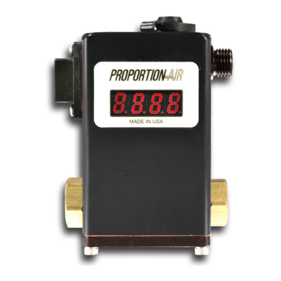
DESCRIPTION / IDENTIFICATION
The QB series valve uses Proportion- Air closed loop technology for
Pressure control. It gives an output pressure proportional to an
electrical command signal input.
The QB1 is a complete closed loop servo system consisting of
valves, manifold, housing and electronic controls. Pressure is
controlled by the use of two solenoid valves. One valve functions as
inlet control, the other as exhaust. The pressure output is measured
by a pressure transducer internal to the QB1 and provides a
feedback signal to the electronic controls. This feedback signal is
compared with the command signal input. A difference between the
two signals causes one of the solenoid valves to open, allowing flow
in or out of the system. Accurate pressure is maintained by
controlling these two valves.
The QB2 is similar to the QB1 but uses a double loop control
scheme. In addition to the internal pressure transducer, the QB2
receives an electrical signal from an external sensing device. This
primary feedback signal is compared against the command signal
input. This comparison is then summed with the internal pressure
transducer signal. The gain of the circuit is such that priority is given
to the external feedback signal. A difference between the command
signal and the feedback signal causes one of the solenoid valves to
be activated.
A monitor output is provided for the system measurement. All QB
valves come standard with an analog voltage monitor output.
QB1 monitor output is an amplified signal from the internal pressure
transducer. QB2 monitor output is a buffered signal from the primary
external transducer connected to the QB2.
For QB valves with model number TFEE or TFIE the monitor output
is voltage. The monitor output is analog current, if the valve model
number is TFEC or TFIC.
details.
INSTALLATION
1.
Apply a small amount of anaerobic sealant (provided) to the
male
threads of the in-line filter supplied with valve.
CAUTION: USE ONLY THE THREAD SEALANT PROVIDED.
OTHER SEALANTS SUCH AS PTFE TAPE AND PIPE DOPE
CAN MIGRATE INTO THE FLUID SYSTEM CAUSING
FAILURES.
2.
Install the in-line filter into the port labeled IN on QB valve.
3.
Connect supply line to the in-line filter port. Connect device
being controlled to port labeled OUT on QB valve.
3.
For vacuum units, the vacuum supply should be connected into
the bottom exhaust port.
4.
Mount valve accordingly.
5.
The valve can be mounted in any position without affecting
performance. Mounting bracket QBT-01 (ordered separately)
can be used to attach valve to a panel or wall surface.
6.
Proceed with electrical connections.
1/5
See ordering information for further
QB1T
SPECIFICATIONS
ELECTRICAL
SUPPLY VOLTAGE 15-24 VDC
SUPPLY CURRENT 250 mA
COMMAND SIGNAL 0-10 VDC | 4-20 mA
COMMAND SIGNAL IMPEDANCE VDC=4.75 KΩ | Current=100 Ω
ANALOG VOLTAGE MONITOR 0-10 VDC
ANALOG CURRENT MONITOR 4-20 mA Sinking (sourcing opt)
MECHANICAL
PRESSURE RANGES Vacuum - 175 psig
OUTPUT PRESSURE† 0-100% of range
FLOW RATE 1.2 SCFM @ 100 psig inlet
Cv CAPACITY 0.04
Min CLOSED END VOLUME 1 in
PORT SIZE 1/8" NPT
FILTRATION RECOMMENDED 40 Micron
LINEARITY/HYSTERESIS <±0.15% F.S. BFSL
REPEATABILITY <±0.02% F.S.
ACCURACY <±0.2% F.S.
WETTED PARTS
ELASTOMERS Fluorocarbon
MANIFOLD Brass
VALVES Nickel Plated Brass
PRESSURE TRANSDUCER Silicon, Aluminum
PHYSICAL
OPERATING TEMERPATURE 32-158°F (0-70°C)
WEIGHT 1.02 lb. (0.50 Kg)
PROTECTION RATING IP65
HOUSING Aluminum
FINISH Black Anodized
† Pressure ranges are customer specified. Output pressures other
than 100% are available. ‡ Others available
QB2T
with Digital Display
(760 mmHg (Vac) - 12 Bar)
(34 L/min @ 6.89 Bar)
3
(included)
‡
QBT Installation Guide - 3/22/2016 | SSS
Advertisement
Table of Contents

Subscribe to Our Youtube Channel
Summary of Contents for Proportion-Air QB1T
- Page 1 INSTALLATION & MAINTENANCE INSTRUCTIONS DESCRIPTION / IDENTIFICATION QB2T with Digital Display QB1T The QB series valve uses Proportion- Air closed loop technology for Pressure control. It gives an output pressure proportional to an electrical command signal input. The QB1 is a complete closed loop servo system consisting of valves, manifold, housing and electronic controls.
- Page 2 RE-CALIBRATION PROCEDURE ELECTRICAL CONNECTIONS Turn off all power to valve. All QB control valves come calibrated from the factory by trained Identify the valve’s command input and analog output using the calibra- personnel using precision calibration equipment. The QB valve is a tion card included in the package and the ordering information section closed loop control valve using a precision electronic pressure on the last page of this sheet.
- Page 3 CURRENT SOURCING MONITOR (ES OR TS) QB2-3D OPTION VALVES Second loop signal is plugged into auxiliary receptacle on opposite side. PIN 6 {BLACK} PIN 1 {GREEN} DC POWER (+) DC COMMON (-) QB2-3D Proportion-Air RECEPTACLE DSY pressure METER transducer H23 COLOR CODE WHITE SIGNAL IN...
- Page 4 Unless certified, Proportion-Air, Inc. products cannot be used with flammable gases or in hazardous environments. AIR QUALITY Clean, dry air is not required for Proportion-Air, Inc. products. However, a 40 micron particulate filter is recommended to prevent solid contamination from entering the product.
Need help?
Do you have a question about the QB1T and is the answer not in the manual?
Questions and answers