Table of Contents
Advertisement
Quick Links
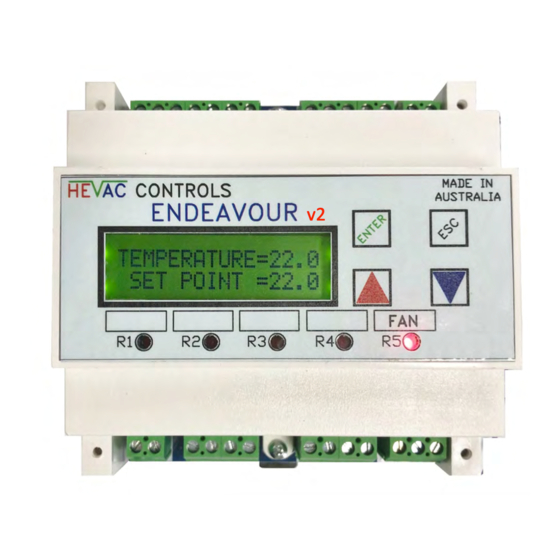
ENDEAVOUR
V2
NEW FEATURES
1.) ADDED INDEPENDENT AUXILIARY TIME SWITCH
2.) EVENT DATA LOGGER
3.) FAN RELAY (R5) SETTABLE AS CONTINUOUS OR CYCLE
4.) ADJUSTABLE MIN. / MAX SETTINGS FOR Y1 & Y2 0-10v O/P's
5.) SUPPLY AIR TEMPERATURE SENSOR MONITORING INPUT
6.) EXTERNAL A/C FAULT (D3) & AUX I/P (D4) BMS MONITORING INPUTS
7.) ACTIVE 0-10vdc SENSORS NOW SCALABLE
8.) ADDED CO2 ON/OFF RELAY CAPABILITY CONTROL.
9.) CAN BE SET TO TIME SWITCH ONLY MODE (-NO TEMP. CONTROL)
10.) LOCKABLE 3 LEVEL MENU & SETPOINT ACCESS
11.) RECLAIM LOCAL SETPOINT CONTROL FROM REMOTE FOR SERVICE
12.) FURTHER ENHANCEMENTS TO HMI CONTROL OF ENDEAVOUR
USER MANUAL
V2
v2
Advertisement
Table of Contents

Summary of Contents for HEVAC ENDEAVOUR V2
- Page 1 ENDEAVOUR USER MANUAL NEW FEATURES 1.) ADDED INDEPENDENT AUXILIARY TIME SWITCH 2.) EVENT DATA LOGGER 3.) FAN RELAY (R5) SETTABLE AS CONTINUOUS OR CYCLE 4.) ADJUSTABLE MIN. / MAX SETTINGS FOR Y1 & Y2 0-10v O/P's 5.) SUPPLY AIR TEMPERATURE SENSOR MONITORING INPUT 6.) EXTERNAL A/C FAULT (D3) &...
-
Page 2: Table Of Contents
INDEX PAGE BASIC OVERVIEW, OVERRIDES & I/O USAGE………………………………………………….. TECHNICAL NOTES …………………………………………………......…………. 4, 5 USER INTERFACE & KEYBOARD LOCK LEVELS………….……...……………………………… MENU DESCRIPTION …..………………............……… CLOCK SETUP - TIME, DATE & DAYLIGHT SAVING ENABLE…….……………………….. SET (A/C SYSTEM) "START BY" METHOD…………….…………………..………………..….. MAIN TIME SWITCH (1) ……….……………………………………………………………….……… AUXILLARY TIME SWITCH (2) ……….……………………………………………………….………... -
Page 3: Basic Overview, Overrides & I/O Usage
OVERVIEW 3/28 • The Hevac ENDEAVOUR is a fully programmable microprocessor based Temperature controller, with optional use of an internal 365 day Time Switch, an independent Auxiliary (+ CO2) Time Switch and a Run Timer all in the one model. The controller has 7 analogue inputs, 4 digital inputs, 5 relay outputs and 2 analogue (0-10vDC) outputs. -
Page 4: Technical Notes
Technical Data Operating Voltage 12 to 24 Volts AC or DC General Specifications Power Consumption 200mA At 24vDC Volts At 24vAC Volts 5 VA Switching Capacity of Relays Voltage AC 0….250 Volts Current 8.0 (2.5) Amps Set point Setting Range 5-35 oC in 0.1 oC Increments Relay Switch ON Points 0.1-19.9 oC... - Page 5 Technical Data (Cont.) Operation Environmental Conditions Ambient Temperature 0...45oC Humidity < 85 % RH (Non Condensing) Storage and Transport Ambient Temperature -5...65oC Humidity < 90 % RH (Non Condensing) COMPLIES TO ALL RELEVENT AUSTRALIAN STANDARDS including 6mm Product Standards segregation between high & low voltage connections Weight 600 grams Including Packaging...
-
Page 6: User Interface & Keyboard Lock Levels
6/28 USER INTERFACE The controllers face plate has four push buttons to access & edit controller settings. “ENTER” ACTS AS THE SAVE OR MENU OPEN BUTTON “ESC” ACTS AS THE EXIT OR JUMP BACK TO PREVIOUS MENU BUTTON “UP & “DOWN” BUTTONS ADJUST SETPOINT, SCROLL MENUS & TO EDIT VALUES. The controller has a backlit (16x2) LCD screen &... -
Page 7: Menu Description
PROGRAM MENUS FUNCTION MENU Set CLOCK TO SET THE CONTROLLERS TIME, DATE AND ENABLE DAY LIGHT SAVING Set "START BY " METHOD : SET SYSTEM ON/OFF OPERATION "BY" the internal TIMESWITCH (1), Internal RUN TIMER (Triggered by remote push button) or by a remote MANUAL ON / OFF SYSTEM SWITCH (by shorting out sensor X1 &... -
Page 8: Clock Setup - Time, Date & Daylight Saving Enable
SET CLOCK (TIME & DATE SETTINGS) To edit the controllers time and date settings, press the fascia button labeled “ENTER” to have the LCD display jump to the 1 menu item in the menu tree…. “SET CLOCK" ENTER Press the button to check and edit the controllers time, date and day light saving enable (or disable) settings Daylight saving, if enabled, starts on the... -
Page 9: Set (A/C System) "Start By" Method
9/28 SET *START BY* METHOD (A/C START / STOP CONTROL) To set the A/C system "START BY" method, press the fascia button labeled “ENTER” then press the DOWN arrow button once to have the LCD display show the 2nd item in the menu tree (after SET CLOCK) : “... -
Page 10: Main Time Switch (1)
10/28 SET MAIN TIME SWITCH (1) The controller's internal main time switch (1) (if enabled for use) can be easily programmed for any combination of ON/OFF switching times for any day of the week. The controller comes preset with factory default settings for operating the system: Monday to Friday from 08:00 (event 01) until 17:30 (event 02). -
Page 11: Auxillary Time Switch (2)
11/28 SET AUXiliary TIME SWITCH (2) The controller's independent Auxiliary Time Switch (2), if enabled for use, can be assigned to any spare relay not used as a Temperature or CO2 on/off control relay, and is assigned to a spare relay in the Relay Programming Menu. The Auxiliary Time Switch is basically intended as a simple auxiliary time switch for controlling other equipment not directly associated with temperature control ie : toilet exhaust fans etc, and is programmed using a more conventional time switch technique with programmable "ON"... -
Page 12: Run /Ahr Timer
12/28 RUN /AHR TIMER Whether the Run Timer is used as a short duration type “After Hours”(AHR) Run timer (if the system normally operates by the controllers internal time switch), or set for a longer period, typically as a “Run For Timer", the procedure to set up the timer is the same. -
Page 13: Event History Data Logger
13/28 VIEW EVENT HISTORY This latest version of the ENDEAVOUR now incorporates a basic event logger that records the last 7 "ON" switching events. example 01 : RELAY 3 ON 15/10/2019 16:30 02 : RELAY 2 ON 15/10/2019 16:50 03 : NIGHT PURGE ON 16/10/2019 04:35 The history can be reset &... - Page 14 14/28 RELAY PARAMETERS PROGRAMMING... continued RELAY SUMMARY SCREEN EXAMPLES = RELAY # (1-4) = MODE OF OPERATION (H,C, B, 0, TIME SW2) = DEADBAND (0-25c) = SWITCHING DIFFERENTIAL(0.1-20c) Tdly = TIME DELAY (0-99 min) CO2 SUMMARY SCREEN A HEATING STAGE SUMMARY SCREEN SETTING SCREEN LABEL DESCRIPTIONS MODE : Sets what control function the relay serves : HEAT, COOL, BOTH,...
-
Page 15: Relay 5 Fan Control Method (Continuous Or Cycle)
15/28 R5 FAN CONTROL METHOD Another update with this latest version of the ENDEAVOUR is the ability to choose, whilst this air conditioning system is enabled to run (whether that be "ON BY" : Time Switch, Run Timer or set to operate by Manual on/off switch), that the fan relay - R5, can be set to remain ON continuously (default) during the ON running period of the system or for the fan (R5) be set to cycle on &... - Page 16 16/28 Y1 & Y2 ANALOGUE (OUTPUTS) PROGRAMMING .CONTINUED EXAMPLE OF ANALOGUE SUMMARY SCREEN = ANALOGUE O/P # (Y1 or Y2) = MODE OF OPERATION (H,C or B) = DEADBAND (0-25c) = PROPOTIONAL BAND (1-25c) = INTEGRAL TIME (1-60min or -P- only) MODE : Y output used as a Heating O/P, a Cooling O/P or set to act as BOTH a Heating &...
-
Page 17: X1 Main Temp. Sensor Configuration
X1 is the main temperature sensor input that the operating setpoint relates to. The input can be set either as a Passive (Hevac type -D sensors) (default) or as an Active type (0-10vdc) in software but must also be selected as a passive or active type in hardware with a small jumper (CN1) on the bottom circuit board to match the software setting. -
Page 18: X3 Outside Air Temp. Sensor Configuration
18/28 X3 O/AIR TEMPerature SENSOR CONFIGURATION Economy cycle operation using analogue output Y1 can be interlocked with an outside air temperature sensor (either passive or active) connected to terminal X3, such that the use of a modulating motorised economy cycle damper set is inhibited for temperature control unless the outside air temperature is more favorable for temperature control then using recycled air from the controlled space. -
Page 19: X4 Auxiliary Temperature (Measurement Only) Sensor
3rd party BMS suppliers. The input can be set as either a Passive (Hevac type -D sensors) or as Active type (0-10vdc) in software but must also be selected as a passive or active type in hardware with a small jumper (CN2-2) on the bottom circuit board to match the software setting. -
Page 20: X7 Co2 Sensor Enable & Y1 Econ.cycle Override Settings
20/28 X7 CO2 ECONOMY CYCLE OVERRIDE SETTINGS Enable this feature if a CO2 sensor is connected to the controller for air quantity control to reduce CO2 build up, by either overriding the economy cycle damper operation connected to analogue output terminal Y1 (to increase fresh air intake) or / &... -
Page 21: Night Purge Ventilation Setup
21/28 ENABLE NIGHT PURGE With this feature enabled it is possible to setup a low running cost building night time ventilation purge cycle, to vent built up heat from within the building with cooler outside air in order to reduce the cost of mechanical cooling during occupancy hours at startup. -
Page 22: Modbus Setup & Memory Map
22/28 MODBUS SETUP & MEMORY MAP Modbus connections X5 (A) & X6 (B) are factory enabled by default using the bottom circuit board input pins CN3-1&2. NOTE If X7 isnt used for CO2 measurement , X7 can be set as ground source for the modbus shield connection by setting input pin CN4 to the "C"... -
Page 23: Controller Main Mode Of Operation - T/Sw. Or Temp Control
23/28 SET CONTROL APPLICATION The Endeavour controller can now be set to operate in a time switch only mode inhibiting most other control functions other then time switches & timers. Functions enabled : Time Switch 1, Time Switch 2 , Run Timer & AUTO /OFF / ON system overrides modes. Under this menu select "STANDARD TEMP. -
Page 24: Typical Connections & External Interlocks Overview
Typical Wiring Connections AVAILABLE SENSORS OPERATIONAL NOTES: 2 WIRE SRT-D ROOM TEMPERATURE SENSOR SRT-DSW 2 WIRE " + ON/OFF SWITCH If a remote setpoint device is connected (X2) SRT-DSP " C/W SETPOINT POT. 3 WIRE then local setpoint control (via Controllers UP SRT-DSPSW 3 WIRE "... -
Page 25: User Program Information Forms
25/28 FACTORY SET ENDEAVOUR SITE PROGRAM INFORMATION TIME SWITCH CONTROLLER SET TO “RUN BY” : _____ ______________ ENABLED DAYLIGHT SAVING = or DISABLED 2 HOURS RUN TIMER SETTING = M T W T F S S YES(Y) or NO(-) TIME SWITCH 1 EVENT 01, DAYS : TIME:____ 8 _:0 _ __ _... - Page 26 26/28 ENDEAVOUR SITE PROGRAM INFORMATION (PLEASE RECORD SETTINGS IF CONTROLLER CHANGED FROM FACTORY DEFAULTS & LEAVE ONSITE.) CONTROLLER SET TO “RUN BY” : _______________________________ DAYLIGHT SAVING = ENABLED or DISABLED RUN TIMER SETTING ____________ M T W T F S S YES(Y) or NO(-) TIME SWITCH 1 EVENT 01, DAYS : TIME:_____:_____, ACTION: ON OFF EVENT 02...
- Page 27 27/28 RELAY 1 – 4 RELAY ASSIGNMENTS RELAY I MODE I DEADBAND(DB) I SWITCH. DIFF.(SD) I TIME DELAY (Tdly) I NOTES I_________I______________I________________I_________________I______________________ I_________I______________I________________I_________________I______________________ I_________I______________I________________I_________________I______________________ I_________I______________I________________I_________________I______________________ RELAY 5 FAN CONTROL METHOD: ON or CYCLE Y1 & Y2 ANALOGUE OUTPUT ASSIGNMENTS ANALOG O/P MODE DEADBAND(DB) PROP.BAND (PB)
Need help?
Do you have a question about the ENDEAVOUR V2 and is the answer not in the manual?
Questions and answers