
Summary of Contents for Artifex TZA500 Series
- Page 1 Artifex Engineering TZA500 Series Transimpedance Amplifier Read this instruction manual before performing any task!
- Page 2 TZA500 Operating Instructions Original Operating Instructions Artifex Engineering e.K., 2016 2 / 51...
-
Page 3: Table Of Contents
TZA500 Operating Instructions Table of Contents ABOUT THIS MANUAL Information about this manual Explanation of symbols Copyright Customer service SAFETY Intended use Basic dangers Responsibility of the owner Personnel requirements Symbols on the unit Scope of delivery Transport inspection Packaging Transporting 2.10 Storage... - Page 4 TZA500 Operating Instructions 6.3.1 Input Receptacle 6.3.2 Output Receptacle 6.3.3 Overload Indicator (red LED) 6.3.4 Power Indicator (green LED) 6.3.5 Bias Receptacle Back Panel 6.4.1 Hardwire Interface (DB25 Receptacle) 6.4.2 USB Receptacle 6.4.3 Power Input Receptacle PRINCIPLES OF OPERATION Input Receptacle Bias Receptacle Gain Output Polarity...
- Page 5 TZA500 Operating Instructions 10.8 Source Code of the Application Programme 10.9 Demo Programm in Labview COMMUNICATION WITH THE TZA500 11.1 Communication Protocol 11.2 Command Structure 11.2.1 Change Interface 11.2.2 Data output 11.2.3 Auto-Zero Function 11.2.4 Polarity 11.2.5 Bandwidth 11.2.6 Info 11.2.7 Gain DAMAGE...
- Page 6 TZA500 Operating Instructions List of Figures Figure 1: Case Dimensions; units mm (inches) ............... 22 Figure 2: Front Panel (BNC input, no bias) ................22 Figure 3: Front Panel (BR2 input, with bias receptacle)............23 Figure 4: Polarity of Input Receptacles for Positive Output in Non-Inverting Mode....23 Figure 5: Pinning of the Bias Receptacle .................
-
Page 7: About This Manual
TZA500 Operating Instructions 1 About this manual 1.1 Information about this manual This manual is valid for units with firmware version FW2.0, that is, with serial number S/N 131 and higher. This manual enables you to handle the device in a safe and efficient manner. This manual is part of the device and must be kept in its vicinity in order to ensure that it is available to the personnel at all times. - Page 8 TZA500 Operating Instructions CAUTION! This combination of symbol and signal word indicates a possibly- dangerous situation which could cause slight injuries if it is not avoided. NOTICE! This combination of symbol and signal word indicates a possibly-dangerous situation which could cause property and environmental damage if it is not avoided.
-
Page 9: Copyright
TZA500 Operating Instructions 1.3 Copyright The contents of these instructions are copyrighted. Their use is permitted in the context of using the device. Any use extending beyond this is not allowed without written permission from the manufacturer. 9 / 51... -
Page 10: Safety
TZA500 Operating Instructions 2 Safety This section provides an overview of all safety aspects that are essential to the best possible protection of the personnel and the safe and trouble-free operation of the machine. Additional safety instructions for specific work tasks are contained in the sections regarding the individual life stages of the machine. -
Page 11: Responsibility Of The Owner
TZA500 Operating Instructions 2.3 Responsibility of the owner Owner: The owner is any such person who operates the transimpedance amplifier for commercial or economic purpose either itself or transfers it to a third party for use and bears the legal responsibility for the safety of the user, the personnel or third parties during the operation. -
Page 12: Personnel Requirements
TZA500 Operating Instructions 2.4 Personnel requirements Qualifications: The various tasks described in this manual place different requirements on the qualification of the persons to whom these tasks are entrusted. NOTICE! Insufficiently qualified personnel can cause property damage! Insufficiently qualified personnel cannot assess the risks when working with the unit. -
Page 13: Symbols On The Unit
TZA500 Operating Instructions 2.5 Symbols on the unit The following symbols and instruction signs are affixed in the work area. These symbols and instruction signs refer to the immediate vicinity in which they are affixed. WARNING! Danger due to illegible signage! ... -
Page 14: Scope Of Delivery
TZA500 Operating Instructions 2.6 Scope of delivery Depending of the chosen model, the scope of delivery will vary: TZA500 transimpedance amplifier Power supply USB cable USB-Stick with Software, drivers and manual Bias shorting adapter plug (models with bias receptacle only) ... -
Page 15: Transporting
TZA500 Operating Instructions Handling packaging materials If the transimpedance amplifier no longer has to be transported, dispose of the packaging materials in accordance with the respective statutory provisions and local regulations. NOTICE! Danger for the environment from improper disposal! Packaging materials are valuable raw materials and can be reused in many cases or prepared and recycled. -
Page 16: Storage
TZA500 Operating Instructions 2.10 Storage Store the electronic ballasts in the packaging under the following conditions: Do not store outdoors. Store in a dry and dust-free area. Do not expose to any aggressive media. Protect from sun radiation. ... -
Page 17: Product Overview
The use of logarithmic amplifiers for optical power monitoring results from the large dynamic range of relevant powers. For example, the TZA500 series can measure from 10mA to 30pA: more than 8 decades of current (or optical power when measuring photodiodes). This dynamic range is far beyond the capabilities of a linear amplifier in a single gain range. - Page 18 TZA500 Operating Instructions 1. Linear amplifiers are more stable than logarithmic amplifiers 2. Linear amplifiers are faster than logarithmic amplifiers and settle more quickly following sudden input changes 3. Linear amplifiers are more accurate than logarithmic amplifiers at higher outputs Consider an application example: a fibre optic power monitor is used to measure the power coupled into a device in an automated confectioning system.
-
Page 19: Absolute Maximum Ratings
TZA500 Operating Instructions 4 Absolute Maximum Ratings Table 1: Absolute Maximum Ratings Average Input Current 15mA Input Voltage ±15V Bias Voltage ±15V Temperature Range 0 – 60 °C 5 Ordering Information Table 2: Ordering Information Full order code: TZA500 Options Description Input Differential... -
Page 20: Specifications
TZA500 Operating Instructions 6 Specifications Table 4: Specifications of the TZA500 Parameter Conditions Units Input Current ranges (full scale) Range: “ µA “ “ Noise equivalent current (NEI Range: “ “ “ “ Impedance 0 (virtual short circuit) Connectors BNC or BR2 Output Function... -
Page 21: Typical Signal Forms
TZA500 Operating Instructions 6.1 Typical Signal Forms Table 5: Typical Signal Forms TZA500SBbias: small signal from 70pF source TZA500SBbias: large signal from 70pF source (single ended, BNC input, with bias receptacle) (single ended, BNC input, with bias receptacle) TZA500SBbias: small signal from 2nF source TZA500SBbias: large signal from 2nF source (single ended, BNC input, with bias receptacle) (single ended, BNC input, with bias receptacle) -
Page 22: Case Dimensions
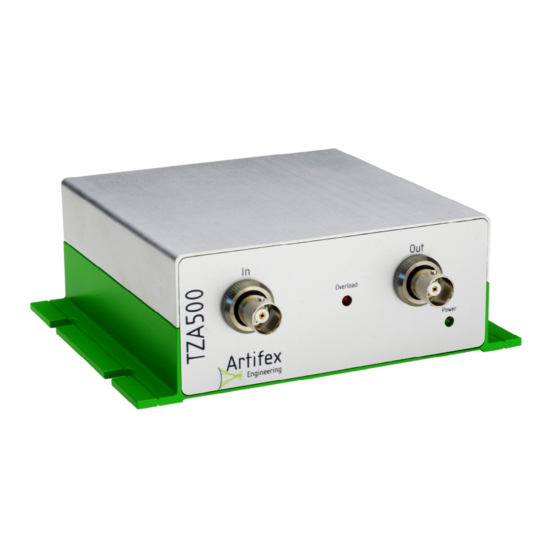
TZA500 Operating Instructions 6.2 Case Dimensions Figure 1: Case Dimensions; units mm (inches) 6.3 Front Panel Output receptacle Input receptacle Power indicator Overload indicator (green LED) (red LED) Figure 2: Front Panel (BNC input, no bias) 22 / 51... -
Page 23: Input Receptacle
TZA500 Operating Instructions Output receptacle Input receptacle Power indicator Overload indicator Bias receptacle (green LED) (red LED) Figure 3: Front Panel (BR2 input, with bias receptacle) 6.3.1 Input Receptacle This receptacle is used to input current for measurement. The receptacle may be BNC or BR2. With the amplifier in non-inverting mode, the output will be positive when a current source is connected to the inner pin of the BNC receptacle or the left input of the BR2 receptacle. -
Page 24: Power Indicator (Green Led)
TZA500 Operating Instructions 6.3.4 Power Indicator (green LED) The power indicator is lit if the unit is powered on. There is no ON/OFF switch on the TZA500. The unit is powered on when the power supply is connected to the instrument and to the mains. -
Page 25: Back Panel
TZA500 Operating Instructions 6.4 Back Panel Power input receptacle Hardwire interface Figure 7: Back Panel receptacle (DB25 receptacle) 6.4.1 Hardwire Interface (DB25 Receptacle) The hardwire interface is provided for direct, high speed control of the TZA500 via an external switching device such as an A/D-interface card. This interface is described in detail under “8 Hardwire Interface”, pg. -
Page 26: Principles Of Operation
TZA500 Operating Instructions 7 Principles of Operation The TZA500 measures small currents e.g. optical power via a photodiode. Photodiodes are useful for power measurement in the visible and near infra-red due to their inherent sensitivity and speed of measurement. Photodiodes produce a current which is proportional to the incident light power over a wide dynamic range. -
Page 27: Input Receptacle
TZA500 Operating Instructions 7.1 Input Receptacle This receptacle is used to input current for measurement. The receptacle may be BNC or BR2. With the amplifier in non-inverting mode, the output will be positive when a current source is connected to the inner pin of the BNC receptacle or the left input of the BR2 receptacle. Current source Current source (photodiode anode) -
Page 28: Bias Receptacle
TZA500 Operating Instructions 7.2 Bias Receptacle TZA500 models with a bias receptacle allow application of an external bias voltage to the device under test. This can be important to ensure full charge depletion in some photoactive devices resulting in more accurate readings when sampling at high speed. The shorting plug adapter must be inserted if an amplifier with bias receptacle is used without an external bias source connected. -
Page 29: Output Polarity
TZA500 Operating Instructions 7.4 Output Polarity The TZA500 allows simple switching of the polarity of the output signal. This is valid for the analogue voltage outputs (BNC and DB25) as well as the values displayed on the GUI. This function is useful for ensuring a positive output when for example an external A/D-converter is used. - Page 30 TZA500 Operating Instructions Activation of the auto-zero function does not affect the voltage range of the amplifier. For example, if the auto-zero is activated when 3V are output, then the outut is reduced to 0V and the remaining dynamic range of the amplifier is 7V. Pin 23 of the DB25 interface provides a logic control signal for this function.
-
Page 31: Hardwire Interface
TZA500 Operating Instructions 8 Hardwire Interface The hardwire interface (DB25 connector) is active upon starting the TZA500. This interface has two galvanically isolated grounds. The analogue ground (pin 3) is the reference point for the analogue signals (pin 6 and pin 25). The digital ground (pin 9) is the reference for all digital inputs and outputs. -
Page 32: Installation Of The Software Package
TZA500 Operating Instructions 9 Installation of the Software Package The installation of the software package is described in a separate document provided with the instrument. 10 Using the Application Software The graphical user interface (GUI) is simple and easy to use. All of the important features can be reached directly in the main window. - Page 33 TZA500 Operating Instructions Save as – This function always prompts for the file name and folder. Otherwise identical to “Save”. Export – Exports the present graph frame into a graphic file in one of the following formats: *.emf, *.png, *.gif , *.jpg, *.tif oder *.bmp. Print –...
- Page 34 TZA500 Operating Instructions Gain: Gain x1 ... Gain x100.000 – Selects the electrical gain of the amplifier. The selected gain is indicated by a check mark. The actual gain of the amplifier is given by the gain multiplier times the base gain of 10 V/A.
-
Page 35: The Tool Bar
TZA500 Operating Instructions 10.2 The Tool Bar The tool bar allows for quick access to the most important functions. Figure 14: The Tool Bar The file handling functions (Load , Save , Print and Copy ) are identical to the corresponding sub menus in the pull down menus. - Page 36 TZA500 Operating Instructions In addition, there are input fields for the sampling period in ms, as well as buttons to select the mode of display (digital and graph modes). Sampling Period: The period of time between two samples can be selected and displayed. This is also accessible in the “Preferences”...
-
Page 37: The Status Bar
TZA500 Operating Instructions 10.3 The Status Bar The most important status information is displayed here. Connection status Bandwidth Selected gain Amplifier output level Figure 15: The Status Bar Connection status: Indicates whether a TZA500 instrument is connected and all relevant connection parameters could be set properly. -
Page 38: Preferences
TZA500 Operating Instructions 10.4 Preferences In addition to the settings in the tool bar, there are several which will not be required during normal operation and will usually be set once when first setting up the instrument. These settings are found in the pull down menu “Edit” under “Preferences”. The following window then appears: Y-Axis, Start at zero: When using automatic Y-axis scaling, the lower limit of the... -
Page 39: Data Formats
TZA500 Operating Instructions 10.5 Data Formats 10.5.1 The *TZA Format The software uses three formats for saving and loading data. The programme specific format *.TZA uses ASCII characters. The file header contains the date and the units of the data values. -
Page 40: The Graph
TZA500 Operating Instructions 10.6 The Graph The graph mode is the default mode which will appear when starting the programme. The X-axis represents the sample number of a measurement sequence, the Y-axis represents the measured current. The units of current automatically adjust to the level being measured. A dynamic zoom can be activated by clicking in the graph window and dragging a box to the size of the desired zoom. -
Page 41: The Context Menü
TZA500 Operating Instructions 10.6.1 The Context Menü The context menu is opened by a right click within the graph frame. Copy A picture of the graph is stored to the PC’s temporary storage. It may be copied into other programmes for documentation purposes. -
Page 42: The Sdk Package
TZA500 Operating Instructions 10.7 The SDK Package The TZA500 comes with a software development kit (SDK package) in order to ease integration of the instrument into OEM projects. This package includes the source code of the application programme (written in Microsoft VB.net version 2005) as well as a LabVIEW VI example. - Page 43 TZA500 Operating Instructions The graph in the main window is generated by embedding the file Graph.dll in the output. For more information, see Hinweis.txt. The programme comprises 6 windows which contain the source code. There are three further modules responsible for the following features: MOD_Communication: This module governs the communication with the TZA500 via the driver libraries.
-
Page 44: Demo Programm In Labview
TZA500 Operating Instructions 10.9 Demo Programm in Labview A LabVIEW demonstration VI is supplied with the instrument to ease integration into LabVIEW environments. The programme is found in the folder \SDK\Labview. All relevant sub-VIs are in the subfolder libraries. Please note that this is a demonstration programme only and is not intended to replace the fully functional main application software. -
Page 45: Communication With The Tza500
TZA500 Operating Instructions 11 Communication with the TZA500 In order to communicate with the TZA500, the driver can be integrated directly into an existing project. Two examples have been given in the description of the SDK package. A simpler method is by designating a COM-port. The driver can generate a virtual port n the control panel. - Page 46 TZA500 Operating Instructions The communication parameters must now be entered in the following window. Confirm the changes by clicking „OK“. If all parameters are correct, an indication will appear at the bottom of the main window that the connection has been successful. This may be checked by typing “$U”. The TZA500 responds with “U-OK”.
-
Page 47: Command Structure
TZA500 Operating Instructions 11.2 Command Structure 11.2.1 Change Interface TTL Interface. The DB25 hardwire interface is activated. Control is made using TTL-compatible signals (Default interface on startup). Response: T OK USB Interface. Control is made using the USB interface. Response: U OK 11.2.2 Data output $P :... -
Page 48: Bandwidth
TZA500 Operating Instructions 11.2.5 Bandwidth bandwidth 10KHz (default) bandwidth 1KHz bandwidth 100Hz bandwidth 10Hz Response: B <Bandwidth> OK Request present bandwidth status Response: B <Bandwidth> 11.2.6 Info $I : Information about the system, serial number and date of manufacture. Response: <Instrument>... -
Page 49: Damage
TZA500 Operating Instructions 12 Damage The unit may be damaged by exceeding the maximum average input power. Please read „4 Absolute Maximum Ratings”, pg. 19 for these maximum values before working with the instrument. 12.1 Troubleshooting In the event that a measurement is not successful, the following possibilities should be analysed: Symptom Possible Errors... -
Page 50: Disposal
TZA500 Operating Instructions 13 Disposal Do not dispose of the TZA500 with the household waste. The worn out unit can be taken to an electronics and metal recycling centre for disposal. The manufacturer also accepts old units for disposal. NOTICE! Danger for the environment from improper disposal! Dangers for the environment can arise through improper disposal. -
Page 51: Notice
15 Notice Artifex Engineering reserves the right to make changes to its products or to discontinue any product or service without notice and advises customers to obtain the latest version of relevant information to verify, before placing orders, that information being relied on is current and complete.
Need help?
Do you have a question about the TZA500 Series and is the answer not in the manual?
Questions and answers