Table of Contents
Advertisement
Quick Links
Advertisement
Table of Contents

Subscribe to Our Youtube Channel
Related Manuals for Genie BS1000


Summary of Contents for Genie BS1000
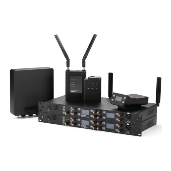
- Page 1 Base Stations BS1000, BS850 Remote Antennas RA100DW, RA100 Repeater RBS85 Speaker Station ISS800 Ethernet Beltpack IBP10 Wireless Beltpack BP850, BP850S Converged Intercom System GENIE User Manual (Version V221011 LaON Technology ⓒ2020 LaON Technology Co., Ltd. All rights reserved.
-
Page 2: Table Of Contents
Base Station BS1000 Base Station BS850 Multi-Sync connections for Ethernet synchronizations. GENIE Connections Daisy-chain ring configuration (Power and data redundancy) Base Station BS1000 Daisy-chain ring configuration (Power and data redundancy) Base Station BS850 Configures a redundancy system WAN Adapter WAN85... - Page 3 9.1 Connecting the wireless Beltpack BP850 , BP850S 9.2 Operating the the wireless Beltpack BP850 , BP850S Section 10: Specifications 10.1 Base Station BS1000 10.2 Base Station BS850 10.3 Remote Antenna RA100DW 10.4 Remote Antenna RA100 10.5 Repeater RBS85 10.6 Speaker Station ISS800 10.7 Ethernet Beltpack IBP10...
- Page 4 7.9 inches (20 cm) from the antenna to the body of user required. GENIE system operates in the 5GHz UNII band frequency range. GENIE system is approved for license free use in most countries. There may be restrictions on the use of some bands or RF spectrum operations in some countries.
- Page 5 Copyright © 2019 Laon Technology Co., Ltd. All rights reserved. The products described in this document are distributed under licenses that limit usage, copying, and deployment. The Software described in this document is furnished under a license agreement and does not provide any rights other than restricted licenses.
-
Page 6: Section 1: Introduction
Power of Ethernet (PoE) with one Base Station while supporting the wireless Beltpack connections at the same time. By this boundaryless hybrid solution of wired or wireless, GENIE offers a highly scalable and flexible system configurations and capabilities. -
Page 7: Genie Devices
⚫ Ten talk/listen paths per Base Station or Remote Antenna Each Base Station or Remote Antenna provides 10 additional talk/listen paths. Therefore, one Base Station BS1000 with six Remote Antennas provides up to 70 talk/listen paths for the wireless Beltpacks or GENIE IP devices. - Page 8 Line input and output ports are provided to secure seamless connections with wired intercom systems, external audio devices etc. ⚫ GCM (GENIE Configuration Manager) for setting and monitoring With GCM, users can pair and set each device over the Ethernet connection and monitor the connectivity status of each device.
-
Page 9: Example Of Using Genie System
Beltpacks or Speaker Stations can be connected to a Remote Antenna. With the industry standard LAN network configuration, multiple studios or multi-floor sites can be easily consolidated. ⚫ Base Station BS1000 and Remote Antenna RA100DW provide very efficient functions such as PoE and Daisy- chain connections. The Remote Antenna RA100 does not provide Daisy-chain connections. -
Page 10: Genie Solo Base Station Bs850
GENIE Solo, Base Station BS850 Ten talk/listen paths added per Remote Antenna. A Remote antenna with 128 wireless Beltpacks , and 10 Ethernet Beltpacks or 10 Speaker Stations or 10 Repeaters. 10 talk/listen paths Beltpacks, Speaker Stations or Repeaters can be flexibly... -
Page 11: Base Station Bs850
GENIE devices can be connected in several different ways Daisy-chain ring configuration (Power and data redundancy), Base Station BS1000 BS1000, RA100DW, ISS800 Power and data redundancy: 48VDC, PoE In and Daisy-chain ring connection. IBP10 Power and data redundancy: Daisy-chain ring connection. -
Page 12: Daisy-Chain Ring Configuration (Power And Data Redundancy) Base Station Bs850
Configures a redundancy system (This has been applied to BS1000 version V4030) The redundancy system consists of a redundancy setting and a GENIE Duo system and daisy chain ring connection. One Base Station BS1000 or Remote Antenna in monitoring mode monitors for failure of another Base Station or Remote Antenna. -
Page 13: Genie Group Channels
IFB and IC/ISO communications in one system With the GCM setting of the Base Station BS1000, you can specify the IFB group channel and dim level of the FB audio (Program input). With this setting on the BS1000, when an IFB path is created on a GENIE group channel set as the FB audio, the FB audio is dimmed and mixed with IFB audio. -
Page 14: System Usage With Line Devices With Base Station Bs1000
Master Beltpack (MB) mode ⚫ A Master Beltpack mode consists of only wireless Beltpacks. Only one of the Beltpacks is set as the master and provides the coverage area for other Beltpacks ⚫ A Master Beltpack mode provides a group channel with five talk/listen paths (1 MB + 4 BPs). ⚫... -
Page 15: Section 2: Product Overview
Section 2: Product overview 2.1 GENIE equipment Base Station BS1000 equipment System configured with Base Station BS1000 + Remote Antennas + Ethernet Beltpacks + Speaker Stations + ⚫ wireless Beltpacks + Repeaters. It can also be used in conjunction with the GENIE Panels. -
Page 16: Remote Antenna Ra100Dw Equipment
Remote Antenna RA100DW equipment ⚫ Can be configured with Base Stations BS850 or BS1000. ⚫ Provides an additional 10 talk/listen paths. ⚫ IP53 sealing (Dust + water spray at up to 60° from vertical) and antennas are mounted internally. (IP65 sealing when fixing the power rubber cap with waterproof adhesive) ⚫... -
Page 17: Speaker Station Iss800 Equipment
Speaker Station ISS800 equipment Can be configured with Base Station BS850 or BS1000 through the Remote Antenna ⚫ Power and data redundancy: 2 x 48VDC, PoE In and Daisy-chain ring connection ⚫ 48-56VDC 2.5A Power Supply (One more is available as an option) ➢... -
Page 18: Battery Charger Equipment
Battery charger equipment BATCHG225 Battery Charger BATCHG125 Battery Charger 15VDC 8A Power Supply Headsets and microphones LSH-S125D (Dynamic) LMH-125D (Dynamic) LMH-10 (Dynamic) LNH-20D (Neckband, Dynamic) PTE-850 (Electret) GM8 (7.5inch, Electret) GM26 (17.5~26inch, Electret) ⓒ2020 LaON Technology Co., Ltd. All rights reserved. -
Page 19: Menu Maps
OPTO1 T12345678: Assign the Opto1 input to Talk channels. OPTO2 T12345678: Assign the Opto2 input to Talk channels. Relay1 T12345678) Relay2 T12345678: (This has been applied to BS1000 version V3516) Set Relay1 or Relay2 to Talk key. T1 G12345 ABCD... -
Page 20: Base Station Bs850 Menu
Base Station BS850 menu Normal menu Main menu Sub menu 1 Sub menu 2 Display Main Menu’s item is as Sub menu’s item is as follow Headset Group, follow Lock status Set Gains: Set levels Speaker #: headset volume level AUX I/O Group, Setting the levels Mic #: microphone level... -
Page 21: Speaker Station Iss800 Menu
Speaker Station ISS800 menu Normal menu Main menu Sub menu and Screen 2 Display four Screen 2 Group labels. Display Speaker Station’s label, Paired date, Linked Base Station labels, Model, firmware version, Each Channel Set Gains: GN Mic: Gooseneck microphone level Listen level Setting the levels HS Mic: Headset microphone level... -
Page 22: Wireless Beltpack Bp850, Bp850S Menu
Wireless Beltpack BP850 menu Normal menu Main menu Display RSSI level, Display Beltpack’s Label, Model, firmware version, ID number Linked device symbol, Battery level, Main menu’s item is as follow Latched status, Hands Free On Off: Latched talk enable or disable Group, label, Speaker Volume: Headset Volume level. -
Page 23: Section 3: Installing A System
⚫ Make sure that the network switch is connected only to the ‘PoE In’ port of GENIE device and do not connect it to Daisy-chain PoE Line ports. Otherwise, the GENIE device may possibly be damaged causing the stop of PoE power output and etc due to a cut in the fuse. - Page 24 GENIE devices. ⚫ For use in conjunction with a GENIE Panel, only the GENIE Base Station shall be set to Master. If Panels are used only, set one Panel to Master. Always power on the device that is set to Master first.
- Page 25 In this case, the radio band is set differently. When using GENIE Antenna in a frequency band's LaON ID 1 to 10, the wireless camera uses the radio band with LaON ID 11 to 28. When using GENIE Antenna in the frequency band's LaON IDs 11-28, the wireless camera uses the radio band with LaON IDs 1 to 10.
-
Page 26: Placing The Base Station, Remote Antenna And Repeater
Wireless Beltpacks can roam between Base Station, Remote Antennas, or Repeaters. When the wireless signal begins to weaken due to the distance from an Antenna, the Beltpack automatically connects to the nearest Base Station, Remote Antenna, or Repeater where the wireless signal is strong. Typical GENIE Configurations Wireless Beltpack Speaker Station... -
Page 27: 5Ghz Unii Rf Bands
The following table lists the frequencies that can be used in 5GHz UNII RF bands. The LaON ID of frequency bands currently being used will be shown on the Base Station menu. GENIE which operates in 5GHz is approved for license free use in most countries. However, some countries may restrict the use of some RF band or spectrum operations. -
Page 28: Select Rf Channel
Select RF channel On 5GHz UNII RF bands, there is a separate definition and guideline for RF band to be used in indoor environments. On the Base Station or GCM, select ‘Indoor’ if you use the system in any indoor environments. When using the system at any outdoor environments, ‘Outdoor’... -
Page 29: Section 4: Operating The Base Station Bs1000
Section 4: Operating the Base Station BS1000 4.1 Connecting the Base Station BS1000 31 32 Base Station BS1000: Front Panel Power switch 17. CH4 Talk key (LED indicator) Loudspeaker, 3 watts 18. CH4 Volume, push to call Mic on/off button (LED indicator) 19. - Page 30 32. Ear for rack mounting Ear for rack mounting. Base Station rear panel Base Station BS1000: rear panel 1. 13. Antennas Sleeve on each of the antenna connectors clockwise to tighten them and ensure that the antennas are connected firmly.
- Page 31 1 to 8. When the Talk key set to Relay 1 is pressed, Relay 1 (pin 5,18) is activated. In the same way, pressing the Talk key set to Relay 2, activates Relay 2 (pin 6,19). Relay cannot be set on one Talk key with a GENIE group channel.
- Page 32 17. Multi-Sync connector (1/2” wave dipole, SMA) Multi-Sync connection To use two or more Base Stations with Remote Antennas and Repeaters together in an Antenna coverage zone, Multi-Sync connection, which is described hereafter, should be made for the best communication performance.
-
Page 33: Operating The Base Station Bs1000
4.2 Operating the Base Station BS1000 Controls wireless and wired device connections ⚫ Base Station with 8 Talk keys ⚫ One PoE In and two Daisy-chain PoE Lines (PoE standard power and data). ⚫ Base Station: Front panel 31 32 Power switch 17. - Page 34 11. 13. 15. 17. 20. 22. 25. 27. T1~T8 Talk key (LED indicator) The user can specify that the latch is enabled or disabled on the Talk key. And the user can set the GENIE group channel, Relay, or Opto-isolated Input on the Talk key.
-
Page 35: Menu Controls
Set Gains BSlabel Pair Belt TX Off Slave On Set Base BS1000 V1100 Reset Belt Label D190206 Reset Belt Group You enter Main menu by pressing and releasing the Menu button. The Main menu appears in the first screen, and Base Station label, Radio Tx on/off status, Master/Slave status, Base Station model, Firmware version and paired date from the GCM appears in the second screen. - Page 36 Figure. Label/Group/Pair menu The user can set the Beltpack label and the GENIE group channel in the menu. To set up the Labels and GENIE group channels of Beltpacks, under the Beltpack menu, move to and select Pair Belt. The Pair Belt menu appears, as shown in Figure.
- Page 37 Reset Belt Label Initialize all set labels on the wireless Beltpack. Reset Belt Group Initialize the GENIE group channel settings for the wireless Beltpack. Note: After resetting, the corresponding data stored at the Base Station will be stored as factory defaults.
- Page 38 Using multiple Base Stations in an Antenna coverage zone. The GENIE is designed so multiple Base Stations, Remote Antennas and Repeaters can work in one antenna coverage. To ensure smooth coexistence of these devices, you will need set the Ethernet synchronization and connecting the Multi-Sync cable.
- Page 39 With GCM, you can set the IFB features, and you can set to send the Line input audio back to the Line output. Note: If a GENIE group channel is set on the Line, set the GENIE group channel on the Talk key and do not set the Line on the Talk key.
- Page 40 GENIE group channels, ABCD stands for each Line, and R stands for Relay1, and r stands for Relay 2. Each Talk key can be set one GENIE group channel or Line or Relay. In this menu, use the rotary control (#16) to navigate to each symbol and press rotary control (#10) for setting.
- Page 41 A Label06 B Label07 C Label08 D Label09: Displays labels for the GENIE group channels and Lines set in the GCM. Reset Belt Label Initialize all set labels on the wireless Beltpack. Reset Belt Group Initialize the GENIE group channel settings for the wireless Beltpack.
-
Page 42: Section 5: Operating The Base Station Bs850
Section 5: Operating the Base Station BS850 5.1 Connecting the Base Station BS850 LaON LT850 Front panel of the Base Station 1. Headset connector (6pin Mini-Din Receptacle) The headset is with ‘Push-Pull Lock’ type connector. Put a headset into the headset connector on the front panel. - Page 43 4-wire and Multi-Sync connector Connecting to 4-wire When you use with a 4-wire intercom device, plug the enclosed 10 pin spring clamp connector into the ‘4-wire connector’ (#4) on the rear panel of the Base Station, as shown in Figure. Put wires as following wiring map into 10 pins spring clamp connector.
- Page 44 Power switch Power On urn on the Power switch (#5) on the rear panel. ‘DFS detecting’ appear on the screen. The green LED on top of the Talk key (#1) will be flashing slowly indicating the readiness of Base Station to start operations. Normal menu will be displayed.
-
Page 45: Operating The Base Station Bs850
And shows AUX IO when AUX In and AUX Out are enabled both. The number 1 through 5 next to AUX In or AUX IO stands for the GENIE group channel for the auxiliary device that is selected. The letter 'A' indicates that all GENIE groups have been selected. -
Page 46: Menu Menul
Note: The GENIE group channels available on the Base Station can be specified in the Set Group menu. If the same GENIE group channel as the Base Station is set to a 4-wire or AUX IO group channel, it is possible to communicate with the connected intercom devices. - Page 47 Sending), 4WRCV (4-wire receiving). Move to and select Quit or press Set for 2 seconds on any item to return to the Main menu. Speaker 7 Mic Sidetone 5 AUXin 0 AUXout 0 4WSND 0 Figure. Set Gains menu 4WRCV 0 Quit Adjust the volume level Scroll to the Speaker in the menu, press the Set button, and press the Up or Down button to adjust the volume...
- Page 48 Figure. Label/Group/Pair menu The user can set the Beltpack label and GENIE group channel in the menu. To set the Labels and GENIE group channels of Beltpacks, under the Beltpack menu, move to and select Pair Belt. The Pair Belt menu appears, as below.
- Page 49 Pairing icons : No edited data : Pairing can be run with edited data. : The state in which the pair is running. : Paring failed : Paring completed - The Beltpack is now paired and ready for operation. Edit Beltpack labels To set Beltpack Label, move to Beltpack Label (A).
- Page 50 Set button. If the same GENIE group channel as the Base Station (or the Beltpack) is set to a 4-wire or AUX IO group channel, it is possible to communicate with the connected intercom devices.
- Page 51 Using multiple Base Stations in an Antenna coverage zone. The GENIE is designed so multiple Base Stations, Remote Antennas and Repeaters can work in one antenna coverage. To ensure smooth coexistence of these devices, you will need set the Ethernet synchronization and connecting the Multi-Sync cable.
-
Page 52: Section 6: Operating The Remote Antenna And Repeater
⚫ Within 10 devices, Ethernet Beltpacks or Speaker Stations or Repeaters are connected to a Remote Antenna and 128 wireless Beltpacks are also connected. ⚫ 20 GENIE Key Panels can be connected to a Remote Antenna and can be used in conjunction with the GENIE Base Station. - Page 53 Daisy-chain PoE Line1 connector (Ethercon RJ45, PSE) Daisy-chain PoE Line2 connector (Ethercon RJ45, PSE) Provides Daisy-chain connection function to supply data and power from PoE or 48VDC inputs to another PoE Line. PoE Line1 and PoE Line2 provide the ability to use the input power from the PoE or 48VDC inputs and supply the remaining power to the other PoE Line.
-
Page 54: Connecting The Remote Antenna Ra100
Waterproof RJ45 plug assembly diagram (RA100DW) Note: Make sure that the RJ45 cable is fabricated using the connector included (number 1 of the above illustration). Connecting to the water-proof terminal using a conventional RJ45 connector is likely to cause poor connection. Connecting the Remote Antenna RA100 Receive antenna. -
Page 55: Operating The Remote Antenna Ra100Dw, Ra100
2. Status LEDs on the front panel of the Repeater Power LED: Solid green when the PoE is connected. RF Alert LED (#7): When there are audio breakups seriously, RF Alert LED will go on. BS Link LED (#8): This green LED indicates that a data connection has been established with the Base Station. BS Active LED (#9): This flashing LED indicates that the Base Station is receiving data from the Base Station. -
Page 56: Operating The Repeater Rbs85
Receive antenna. 1A. Transmit antenna connector LAN RJ-45 connector with the PoE (PD) Status LEDs Antenna holder (optional) 1. Antenna connectors Put two enclosed antennas to the antenna connectors (#1, #1A) on the top panel of the Remote Antenna. Turn the sleeve on each of the antenna connectors clockwise to tighten them and ensure that the antennas are connected firmly. -
Page 57: Section 7: Operating The Speaker Station Iss800
Section 7: Operating the Speaker Station ISS800 7.1 Connecting the Speaker Station ISS800 Speaker Station ISS800: Front Panel Power switch 17. CH4 Talk key (LED indicator) Loudspeaker, 3 watts 18. CH4 Volume, push to call Mic on/off button (LED indicator) 19. - Page 58 Speaker Station Rear panel Speaker Station ISS800: Rear Panel 1. Sidetone NULL adjustment (Screwdriver) for Line A (2-wire) 5. Sidetone NULL adjustment (Screwdriver) for Line B (2-wire) 2-wire sidetone can be nulled by the screwdriver-adjustable control. To adjust the null control on each 2-wire channel - When using the headset, the Sidetone Null setting, and when using the gooseneck microphone with the loudspeaker, the Sidetone Null setting may have different levels of adjustment.
- Page 59 Assign this Opto-isolated input to the Talk channels. When this input is detected, the corresponding Talk channels are activated. You can assign one Opto-isolated input to multiple Talk channels. One Talk key can be assigned Opto-isolated input functions with GENIE group channels. Relays The Relay output allows the use of a Talk key to trigger any external device that allows standard contact closure.
- Page 60 18. 48VDC 2.5A Power input connector (4-pin Din) 19. 48VDC 2.5A Power input connector for duplex (4-pin Din) Each power input connector is 48-56VDC at a max power of 90Watt. The external PSU provides the 48VDC 2.5A required and at its input takes 100-240VAC, 47-63Hz. A Speaker Station supplies power to itself and PoE Line1 and 2, using power from PoE In or two power input sockets.
-
Page 61: Operating The Speaker Station Iss800
7.2 Operating the Speaker Station ISS800 Speaker Station with 8 Talk keys ⚫ One PoE In and two Daisy-chain PoE Lines (PoE standard power and data). ⚫ Speaker Station: Front panel Speaker Station ISS800: Front Panel Power switch 17. CH4 Talk key (LED indicator) Loudspeaker, 3 watts 18. - Page 62 11. 13. 15. 17. 20. 22. 25. 27. T1~T8 Talk key (LED indicator) The user can specify that the latch is enabled or disabled on the Talk key. And the user can set the GENIE group channel, Relay, or Opto-isolated Input on the Talk key.
-
Page 63: Menu Controls
Menu controls Normal menu The labels and listen levels of the eight Talk channels are displayed on two screens. You can set when the screen automatically turns off. The display will turn off if key is not used or there is no incoming call during a set time period. If there is any operation of the key, the display will turn on again. - Page 64 The user can also set one Line without setting up a GENIE group channel on the Talk key. Note: If a GENIE group channel is set on the Line, set the GENIE group channel on the Talk key and do not set the Line on the Talk key.
- Page 65 Unbalanced Audio Output GND Unbalanced Audio Output One Relay or Line or GENIE group channel can be set on the Talk key 1 in the GCM. Each Talk key can be set one GENIE group channel or Line or Relay.
-
Page 66: Section 8: Operating The Ethernet Beltpack Ibp10
Section 8: Operating the Ethernet Beltpack IBP10 8.1 Connecting the Ethernet Beltpack IBP10 Ethernet Beltpack for 8 Talk channels with 4 Talk keys. ⚫ Two Daisy-chain ring PoE Lines (PoE standard power and data) ⚫ 6-pin connector headset port and TRS headset port (Mic and Earphone) ⚫... -
Page 67: Operating The Ethernet Beltpack Ibp10
1. 2. 3. 4. Talk keys (LED indicator) The user can specify that the latch is enabled or disabled on the Talk key. And the user can set the GENIE group channel, Relay, or Opto-isolated Input on the Talk key. - Page 68 Menu button Press to display the menu. Navigate to the menu item with Left/Right (#8, #9) button and change the setting to Up/Down (#6, #7) button. Press the Menu button again to return to the Normal screen. Lock the Menu Press the Menu button for 3 seconds to lock or unlock the menu.
- Page 69 Talk5 LaON001 15 Talk6 LaON001 21 Talk7 LaON001 22 Talk8 LaON001 23 Labels for Talk channels 1 through 8, connected Base Station number, and assigned GENIE group channel are displayed sequentially. Rotate Display menu Set Rotate Display You can set the Beltpack display to rotate according to its physical position.
-
Page 70: Section 9: Operating The Wireless Beltpack Bp850, Bp850S
Section 9: Operating the wireless Beltpack BP850, BP850S 9.1 Connecting the wireless Beltpack BP850, BP850S Battery sled BAT50: 2450mAH, ~500 cycles BAT50R: 2000mAH, ~2000 cycles Rechargeable Battery Pack 1. Headset connector (Receptacle) 6. Volume up /Menu scroll button 2. Display screen 7. -
Page 71: Operating The The Wireless Beltpack Bp850, Bp850S
‘ID number of the Repeater’ will be shown. When the Beltpack is connected to the Master Beltpack, ‘MB’ will be shown. The item ‘C’ indicates the GENIE group channel. The numbers 1 through 5 stands for the number of the GENIE group channels. - Page 72 How to control menus Main menu Press any button if the screen is in sleep mode, then the Normal menu appears. For BP850, the Main menu appears when you press the Set button in the Normal menu. For BP850S, the Main menu appears when you press the Set button for more than 3 seconds in the Normal menu, and a quickly tapping it will display the Volume menu for each Talk channel.
- Page 73 Note: Headset safety ⚫ Note that there may be various causes of cut-off of the microphone level, echoing or distortion of the headset. The initial setup recommends that you begin to adjust at a lower level for safe use and improve the level to meet the best levels required for various site environments.
- Page 74 Speaker volume menu in Two groups mode In the Two groups, the listen level for each group will be adjustable individually in each menu as shown above. If you press the Up and Down button in the Normal menu, it can be adjusted the listen level of both groups together.
- Page 75 Normal menu in Master Beltpack (MB) mode Main menu Tx Power 0dB +3dB Figure. Master Beltpack (MB) menus shown sequentially The symbol of the Antenna to which the Beltpack is connected is displayed in the Normal menu. When the Beltpack is connected to the Master Beltpack, 'MB' appears in the Normal menu. The following is the menu of the Beltpack connected to the Master Beltpack.
- Page 76 Pairing with Master Beltpack Beltpacks already paired with Base Station or Mobile Station are automatically connected to the Master Beltpack when the group channel is selected as group 1, and any additional pairing is not required. If you need to pair the Beltpacks with the Master Beltpack, follow the procedure below. In any case, the Beltpack should initially be paired with Base Station.
- Page 77 When the TTA is enabled, pressing the Talk key for more than 2 seconds activates the TTA function. Perform simultaneous transmission to all available GENIE group channels assigned to the Beltpack. The LED turns red. Release the Talk key to stop the TTA transmission. If the TTA is enabled even if the Talk key is set to Hands-free off (Momentary), the Talk key is automatically set to Hands free on (Latched) mode.
-
Page 78: Section 10: Specifications
Section 10: Specifications 10.1 Base Station BS1000 RF Frequency UNII band: 5.16GHz~5.34GHz, 5.48GHz~5.70GHz, 5.745GHz~5.865GHz Antenna Two external 1/2 -wave dipole, SMA female Transmitter Modulation Type QPSK Frequency Stability ± 2ppm Receiver RF Sensitivity -85dBm for 5 BER Frequency Stability ± 2ppm 128 Beltpacks can be paired with a Base Station. -
Page 79: Base Station Bs1000
128 Beltpacks can be paired with a Base Station. It supports 10 talk/listen paths at the Beltpacks per Base Station same time. Including Base Station, eleven talk/listen paths are provided. GENIE group channels Five (5) Audio Bandwidth 200 Hz to 7.2 kHz Audio Dynamic Range >70dB... -
Page 80: Remote Antenna Ra100Dw
10.3 Remote Antenna RA100DW RF Frequency UNII band: 5.16GHz~5.34GHz, 5.48GHz~5.70GHz, 5.745GHz~5.865GHz Antenna Internal Transmitter Modulation Type QPSK Frequency Stability ± 2ppm Receiver RF Sensitivity -85dBm for 5 BER Frequency Stability ± 2ppm Beltpacks per Remote Antenna 128 Beltpacks can be connected and supports the additional 10 talk/listen paths. PoE RJ-45 Connector, 1Gbps/100Mbps Standard PoE specification PoE Input PoE Line1,... -
Page 81: Speaker Station Iss800
10.6 Speaker Station ISS800 GENIE group channels Five ~ Ten Audio Bandwidth 200 Hz to 7.2 kHz Audio Dynamic Range >70dB >95dB @ 1Khz Loudspeaker 3 watts Headset output 500mW into 32 Ohm Front Panel Display Two OLED, 128 x 64 Resolutions... -
Page 82: Wireless Beltpack Bp850
Master Belt Pack mode the same time. Including one Master Beltpack, five talk/listen paths are provided. One group channel is available for the Master Beltpack mode. GENIE group channels Five Number of talk/listen Paths BP850: Two simultaneous talk/listen paths or five selectable paths... -
Page 83: Rechargeable Battery Pack
10.11 Rechargeable battery pack BAT-150 Battery Pack Battery type 7.2V 2450mAH NiMH rechargeable battery pack Charging cycles ~500 cycles -4 ℉ - 104℉ (-20℃ – 40℃) Storage Temperature Weight 0.45 lb (206g) BAT-50 Battery Pack Battery type 2.4V 2450mAH NiMH rechargeable battery pack Charging cycles ~500 cycles -4 ℉... -
Page 84: Section 11: Glossary
Section 11: Glossary Talk channel: If GENIE group channel or Line to be connected is set to the Talk key, this Talk key is called the Talk channel. GENIE group channel: A function provided by the GENIE Base Station (BS1000 or BS850), a group that allows more than one person to have full-duplex conversations at the same time. -
Page 85: Section 12: Factory Default Setting
(MAN) and wide area networks (WAN). Pair: GENIE Panels are registered to the GCM over the LAN. This pairing process allows Panels to recognize each other and an own cryptic code will be given for the corresponding system. - Page 86 Thank you. LaON Technology Co., Ltd. www.laon-tech.com ⓒ2020 LaON Technology Co., Ltd. All rights reserved.
Need help?
Do you have a question about the BS1000 and is the answer not in the manual?
Questions and answers