Table of Contents
Advertisement
Quick Links
AOM EAN ELECTROSTATIC FILTERS
EQUIPMENT SPECIFICATIONS
Table of contents
1
DESCRIPTION . ...................................................................................................................................................................................... 2
2
GENERAL SPECIFICATIONS . ................................................................................................................................................................. 2
3
DIMENSIONS . ....................................................................................................................................................................................... 4
3.1
EAN 200 . ...................................................................................................................................................................................... 4
3.2
EAN 300 . ....................................................................................................................................................................................... 5
3.3
EAN400 ....................................................................................................................................................................................... 6
3.4
EAN600 ........................................................................................................................................................................................ 7
4
COMPONENTS ..................................................................................................................................................................................... 8
5
GENERAL FUNCTION OVERVIEW . ........................................................................................................................................................ 9
6
CERTIFICATION AND TESTING . ........................................................................................................................................................... 1 0
7
INSTALLATION GUIDELINES . .............................................................................................................................................................. 11
7.1
General ....................................................................................................................................................................................... 11
7.2
Delivery and handover ................................................................................................................................................................ 1 2
7.3
Receiving .................................................................................................................................................................................... 1 2
7.4
Unpacking . .................................................................................................................................................................................. 1 2
7.5
Storage . ...................................................................................................................................................................................... 1 2
7.6
Installation scenarios . .................................................................................................................................................................. 13
7.7
Installation .................................................................................................................................................................................. 13
7.8
Access requirements ................................................................................................................................................................... 1 4
7.9
Electrical connection ................................................................................................................................................................... 1 5
7.10
BMS connection . ......................................................................................................................................................................... 1 6
7.11
Prior to Powering the unit ON ..................................................................................................................................................... 1 6
7.12
Powering the unit ON . ................................................................................................................................................................. 1 6
8
OPERATION AND MAINTENANCE ...................................................................................................................................................... 17
8.1
Prior to cooking start . .................................................................................................................................................................. 17
8.2
Cleaning . ..................................................................................................................................................................................... 17
8.3
Troubleshooting.......................................................................................................................................................................... 1 8
9
WARRANTY AND CONTACTS.............................................................................................................................................................. 1 9
9.1
Product Warranty . ....................................................................................................................................................................... 1 9
9.2
Contacts ..................................................................................................................................................................................... 1 9
AOM AUSTRALIA ASSUMES THAT THIS DOCUMENT HAS BEEN TRANSFERRED TO THE PRODUCT OWNER AND
THAT THE OWNER IS FULLY AWARE OF ITS CONTENT
21/54 Beach Street Kogarah NSW 2217 Tel Sales 1300 903 788 Service 1300 904 088
rev 1, 22/09/2016
AOM AUSTRALIA
www.aomaus.com.au email info@aomaus.com.au
1
Advertisement
Table of Contents

Related Manuals for AOM EAN

Summary of Contents for AOM EAN
-
Page 1: Table Of Contents
1 DESCRIPTION ....................................... 2 2 GENERAL SPECIFICATIONS .................................. 2 3 DIMENSIONS ...................................... 4 3.1 EAN 200 ....................................... 4 3.2 EAN 300 ...................................... 5 3.3 EAN400 ....................................... 6 3.4 EAN600 ...................................... 7 4 COMPONENTS ..................................... 8 5 GENERAL FUNCTION OVERVIEW ................................. 9 6 CERTIFICATION AND TESTING ................................ 1 0 ... -
Page 2: Description
DESCRIPTION The EAN Series ESP, our high performance kitchen exhaust Electrostatic Precipitators, provide effective containment for air pollutants and prevent the build‐up of flammable hazards. It also reduces air duct cleaning maintenance while keeping the air free of irritating smoke and greasy odour. Our air cleaners are designed based on the principle of ESP “Electrostatic Precipitation”. The ESP removes fine particles by charging the particles first and subsequently precipitating them into collector cells. The EAN Series Electrostatic Filters have been installed to treat the kitchen exhaust of a large range of commercial kitchens Worldwide as well as throughout Australia and New Zealand. Please contact your AOM representative for project examples. The EAN models available are EAN 200, EAN 400, EAN 600, EAN 660 T, EAN 800 and EAN 1200. More detailed specifications are available for each EAN model type. GENERAL SPECIFICATIONS Note: The product specifications on the next page have been prepared for the stand alone EAN models EAN 200, EAN 300, EAN 400 and EAN 600. These models can be combined to form different spatial arangements and higher airflows as follows: ‐ The EAN 600T is composed on two EAN 300s bolted one on top of each other using the provided fixing points. The EAN 600T specifications are therefore equivalent to two EAN 300s. ‐ The EAN 800 is composed on two EAN 400s bolted one on top of each other using the provided fixing points. The EAN 800 specifications are therefore equivalent to two EAN 400s. ‐ The EAN 1200 is composed on two EAN 600s bolted one on top of each other using the provided fixing points. The EAN 1200 specifications are therefore equivalent to two EAN 600s. AOM AUSTRALIA 21/54 Beach Street Kogarah NSW 2217 Tel Sales 1300 903 788 Service 1300 904 088 www.aomaus.com.au email info@aomaus.com.au ... - Page 3 EAN Model EAN 200 EAN 300 EAN 400 EAN 600 Weight (kg) 60 kg 75 kg 90 kg 120 kg Airflow (l/s) Maximum airflow for: Up to 945 l/s Up to 1415 l/s Up to 1890 l/s Up to 2800 l/s Type 3, Type 6 or light depending on the depending on the depending on the depending on the Type 4 cooking situation* situation* situation* situation* Recommended airflow 470 l/s (Speed through 725 l/s (Speed through 1000 l/s (Speed 1500 l/s (Speed through for: filter 2.2 m/s, ...
-
Page 4: Dimensions
DIMENSIONS EAN 200 AOM AUSTRALIA 21/54 Beach Street Kogarah NSW 2217 Tel Sales 1300 903 788 Service 1300 904 088 www.aomaus.com.au email info@aomaus.com.au 4 rev 1, 22/09/2016 ... -
Page 5: Ean 300
EAN 300 AOM AUSTRALIA 21/54 Beach Street Kogarah NSW 2217 Tel Sales 1300 903 788 Service 1300 904 088 www.aomaus.com.au email info@aomaus.com.au 5 rev 1, 22/09/2016 ... -
Page 6: Ean400
EAN400 AOM AUSTRALIA 21/54 Beach Street Kogarah NSW 2217 Tel Sales 1300 903 788 Service 1300 904 088 www.aomaus.com.au email info@aomaus.com.au 6 rev 1, 22/09/2016 ... -
Page 7: Ean600
EAN600 AOM AUSTRALIA 21/54 Beach Street Kogarah NSW 2217 Tel Sales 1300 903 788 Service 1300 904 088 www.aomaus.com.au email info@aomaus.com.au 7 rev 1, 22/09/2016 ... -
Page 8: Components
COMPONENTS 4.1.1 Schematic diagrams AOM AUSTRALIA 21/54 Beach Street Kogarah NSW 2217 Tel Sales 1300 903 788 Service 1300 904 088 www.aomaus.com.au email info@aomaus.com.au 8 rev 1, 22/09/2016 ... -
Page 9: General Function Overview
4.1.2 The EAN Series electrostatic precipitator comes together with: ‐ 1 x 1 meter power cord ‐ 1 x set of keys ‐ Electrostatic cells ‐ Mesh prefilters 4.1.3 List of potentially required replacement parts Voltmeter ESP 010 Amperemeter ESP 020 Indicator LED light (green) ESP 030 Indicator LED light (red) ESP 031 EAN Series Electrostatic High voltage power board ESP 040 Precipitators Printed circuit board ESP 050 Insulator ESP 060 EAN cell springs (L60mm, D19mm) ESP 070 EAN cell gasket (EAN 400 and EAN 600) ESP 080 Electrostatic Cell for EAN 200 / 400 / 600 ESP 100 Prefilter EAN 200 / 400 / 600 ESP 101 Electrostatic Cell for EAN 300 ... -
Page 10: Certification And Testing
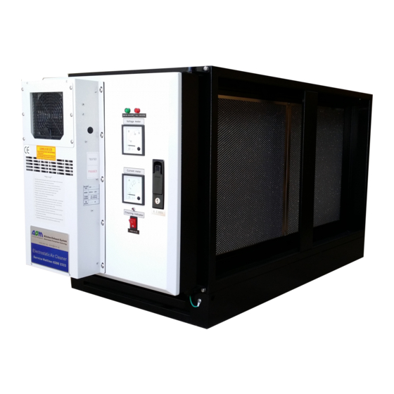
Note: Electrostatic precipitators aim at removing particles, which are responsible for a proportion of total odour discharges. However, gas odour particles remain in the exhaust downstream from the filters. AOM recommends the use of AOM Ozone Generators to inject ozone into the exhaust downstream from the ESP unit in order to mitigate the remaining odour. The overall AOM system has been independently tested as per the requirements of AS1668.2‐2012 and allows for the determination of “deemed airflow rates” and the definition of engineered kitchen exhaust discharge solutions. 5.1.2 Based on the different components, the EAN ESP unit functions as follows ‐ The prefilter acts as a barrier for large grease and other particle material from entering into the electrostatic filter. ‐ The electrostatic cells which function as follows: High Voltage 13 kV tungsten ionising wires which are spring mounted within an aluminium frame distribute an electrical charge to particle matter. Equally spaced low voltage collection plates attract the charged particles. The particles slide down the plates into the tray below. ‐ The electrostatic cells receive high voltage from the EAN ESP unit through the connection insulators located within the unit door. The connection between the cell and the insulator is done using connecting springs located on the ESP cell. The connection between the cells within the unit is done using connecting plates and springs located on the ESP cells. ‐ A removable grease tray collects grease and particle matter that slides down the aluminium plates. ‐ The EAN ESP unit door is equipped with: Lock and door handle to open the door and access the unit electronics Voltmeter indicating the voltage received by the unit Amperemeter indicating the consumed amperage of the unit (see below for the recommended amperage values) ON/OFF switch and indicator lights: Green LED light indicates unit is on, RED LED light indicates that the unit requires cleaning and / or servicing In built cooling fan: ensures that the electronics remain at a constant temperature CERTIFICATION AND TESTING ... -
Page 11: Installation Guidelines
sampling was undertaken before and after an AOM EAN Series electrostatic precipitators with a face velocity of 2.5 m/s and concluded: These results indicate that the kitchen exhaust treatment systems tested are in our opinion capable of achieving an equivalent filtration efficiency of at least 98%. This is assuming regular maintenance is carried out to ensure the systems are operating correctly. 6.1.5 Note: Defined testing ranges follow typical particle sizes for the exhaust emissions from kitchen exhausts as defined in AIRAH Technical Bulletin 2016: Fire Safety Kitchen Hood Exhaust Systems: ‐ Smoke: up to 0.5 micron ‐ Grease steam: 0.5 – 6 micron ‐ Grease splatter: greater than 6 micron 6.1.6 AOM EAN Series Electrostatic Precipitators manufacture filtration efficiency tests were carried out on an EAN 200 electrostatic precipitator based on the efficiency rate test method US Environmental Protection Agency (EPA) / Taiwan Environmental Protection Bureau standard. Testing was carried out on ‘Chinese cooking type’ oil smoke as a testing sample at different speeds through the filter (equivalent to a heavy Type 4 cooking). Filtration efficiency and resistance of the filter was determined for these different speeds as shown on the following graph. 6.1.7 AOM EAN ESP filters are independently certified to the following: ‐ CE certified to European Directive 2004/108/EC for electromagnetic compatibility (certificate available on request). ‐ TUVReinland tested and certified for conducted emissions and radiated emissions based on FCC Part 18. 6.1.8 Independent odour emissions testing of AOM Electrostatic filtration and Ozone injection equipment installed at a ... -
Page 12: Delivery And Handover
7.1.4 Building Code of Australia guidelines should be followed for all hanging and supporting of the equipment. Delivery and handover 7.2.1 Delivery of the equipment will be completed once the full invoiced amount has been received by AOM. 7.2.2 Delivery of the equipment will be completed to the address as indicated by the Client and by means of the agreed logistics. 7.2.3 Unless the client requests otherwise, the delivery will be ensured to the closest suitable access point, at which point the handover of the equipment is complete. 7.2.4 Alternatively, the client can organise to have the product picked up at an AOM warehouse, at which point, hand over is completed. 7.2.5 Unless otherwise mentioned, cost of delivery including freight and any additional handling costs (including crating), are not included in the AOM quoted price and will need to be organised once a delivery address is provided. 7.2.6 The equipment will be delivered at the agreed delivery date and following on from AOM Australia quality control testing on the equipment. Receiving 7.3.1 Upon receiving the product, check to ensure all items are accounted for by referencing the delivery receipt or packing list. 7.3.2 Inspect each crate or carton for shipping damage before accepting delivery. Alert the carrier of any damage detected. The customer will make a notation of damage (or shortage of items) on the delivery receipt and all copies of the bill of lading which is countersigned by the delivering carrier. 7.3.3 If damaged, immediately contact your AOM Representative. Any physical damage to the Electostatic Precipitator after acceptance is not the responsibility of AOM. Unpacking 7.4.1 Verify that all required parts and the correct quantity of each item have been received. 7.4.2 If any items are missing, report shortages to your local Representative to arrange for obtaining missing parts. ... -
Page 13: Installation Scenarios
Installation scenarios Note: The EAN ESP filters can be fireproofed. Only the front panel access door needs to remain accessible. 7.6.1 AOM EAN ESP filters can be installed using different configurations based on the overall total airflow and the requirements of the filtration efficiency. Single pass filtration Stacked Double pass filtration Single pass unit installed outdoors EAN stacked configurations for higher High contaminant exhaust &/or sensitive with a protective weather cover airflows (EAN 600T, 800, 1200) discharge point requires very high filtration efficiency Installation Note: When properly maintained, the Electrostatic Precipitator will ensure high efficiency filtration of smoke and grease particles. To maximise the unit’s capacity, it is recommended to place the units as close as possible to the kitchen exhaust hoods and on the negative side of the fan, thus ensuring that grease is filtered prior. Grease build up in ducts and fans is both a health and safety hazard. Note: The EAN ESP unit can be set up for the airflow from right to left or left to right. When ordering the unit, specify the airflow direction to the AOM Representative. ... -
Page 14: Access Requirements
7.7.4 If the EAN ESP unit cannot be installed next to the exhaust hood, connect the unit with a straight duct of a minimum of one metre on the inlet and outlet side, or if using a bend make sure it is fitted with veins. This will balance the air within the ESP unit. 7.7.5 The airflow volume and air velocity through the EAN ESP unit should be below the rated volume/velocity. See the above equipment specifications for recommended values and contact your AOM Representative for a review of the specific filtration requirements. 7.7.6 The EAN ESP unit should be installed in a horizontal position. The unit should not be installed upside down. If you have nominated an incorrect airflow direction then contact your AOM Representative and they will guide you through the steps to reconfigure the EAN ESP unit. 7.7.7 To ensure high filtration efficiency, the EAN ESP unit should be installed on the negative side of the fan. Air turbulence on the positive side of the fan may decrease the filtration efficiency of the unit. 7.7.8 The EAN ESP unit should be positioned with a minimum separation distance of 1 m from the fan. 7.7.9 Finally, it is recommended that the EAN ESP unit be wired up so that it is automatically powered when the exhaust fan is running. 7.7.10 The EAN ESP unit can be installed outside (on roof tops, along outside duct runs, etc.), however, the unit’s electrical console needs to be covered by a weather proof box. Access requirements 7.8.1 Access to the electrostatic filters needs to be guaranteed in order to ensure removal of the electrostatic cells for cleaning as well as maintenance and troubleshooting of the electrical console box. 7.8.2 All access requirements including panels, hatches, paths and working platforms need to be installed following applicable Occupations Health and Safety Guidelines. 7.8.3 The required maintenances space as shown previously needs to be guaranteed in order to open the ESP unit door and to remove and replace the electrostatic cells. 7.8.4 A general access path of at least 1 m in width needs to be guaranteed from the point of entry to the building to the point of servicing the EAN ESP unit. 7.8.5 The following access requirements need to be guaranteed for different ESP unit locations. ... -
Page 15: Electrical Connection
7.8.7 EAN ESP unit installed in a ceiling space and requiring physical presence inside the ceiling space to be serviced. This implies that the EAN unit is positioned away from the access panel to a point where the service technician needs to physically enter the ceiling cavity to service the machine. ‐ The access panel to the ceiling space needs to meet the above requirements. ‐ A secure access path needs to be guaranteed between the access panel and the EAN ESP unit. ‐ A secure working platform needs to be placed in front of the unit. 7.8.8 EAN ESP unit installed along an open duct, either indoors or outdoors. This generally implies that the EAN ESP units are visible and are located at a certain height that may require the use of a removable working platform (type scissor lift). The available space directly below the EAN ESP unit doors needs to ensure that a safe working platform can be installed in order to service the units. 7.8.9 EAN ESP unit installed in a plant room. An access path from the plantroom entry point to the EAN ESP unit door of a minimum width of 1 m and the minimum door maintenance space in front of the ESP unit’s door as shown in the above figures need to be guaranteed. Should the plantroom be located above level 1, an access lift is recommended in order to decrease the time required for servicing. 7.8.10 EAN ESP unit installed on a rooftop. The overall access from the building entry point to the EAN ESP unit needs to follow the previous recommendations. Access using vertical ladders should be limited to a maximum of 1.5 m in height, since a service technician will need to carry clean and dirty ESP cells weighing between 10‐15 kg. Electrical connection Warning: Though the EAN ESP unit is a plug in and play, it is recommended that the overall electrical installation be carried out by a licenced electrician. 7.9.1 Plug the generator electrical lead to a 10 amp circuit power point. 7.9.2 The power point should be interlocked with the fan switch. When the exhaust fan switch is activated, the voltmeter ... -
Page 16: Bms Connection
7.10 BMS connection 7.10.1 The EAN ESP unit is equipped with two BMS relays within the electrical console (see above figures) which should be connected used a 4 core electrical cable. 7.10.2 The information relayed as well as the AOM standard cable connections are: ‐ POWER: use connection points 1/2 to connect to red/black cable. ‐ FAULT: use connection points 3/4 connect to red/white cable. 7.11 Prior to Powering the unit ON 7.11.1 AOM completes a full system test prior to dispatch of the equipment, meaning that the EAN ESP unit can be plugged in and used immediately. 7.12 Powering the unit ON 7.12.1 Press the switch ON‐OFF to ON. The red LED light will switch on for a few seconds, then the operating green LED will illuminate. 7.12.2 A buzzing sound will indicate that high voltage is running through the electrostatic cells. 7.12.3 The amperemeter will indicate the amperage the unit is drawing in amps: EAN 200 EAN 300 EAN 400 EAN 600 Min: 0.2 amps ... -
Page 17: Operation And Maintenance
OPERATION AND MAINTENANCE Prior to cooking start 8.1.1 AOM recommends however that full mechanical commissioning should be completed prior to cooking in order to ensure that design airflows are respected so that the ESP unit operates within the design capacity. Cleaning Note: An AOM cleaning protocol corresponding to the purchased EAN Series Electrostatic Precipitator is attached to this document and is to be followed by the designated cleaning company. AOM Australia can provide cleaning and maintenance specifically tailored to the requirements of the filtration equipment and to the cooking type. Please contact your AOM Representative to organise this service. Note: Cleaning of the electrostatic precipitators generally requires the additional purchase of replacement cells and potentially prefilters. AOM Australia provides a discounted package price for spare cells and pre filters when: 1. These are purchased together with the EAN ESP unit or; 2. These are purchase if an AOM cleaning contract is signed. It is essential that the end user be made aware of this requirement. 8.2.1 Cleaning and periodic maintenance is vital to ensure optimal performance of the AOM EAN units and minimise service requirements. 8.2.2 In order to ensure efficient cleaning of the filtration equipment (electrostatic cells and potentially the pre filters), it is recommended that spare sets of filters be purchased. Please contact your local AOM Representative to receive further information. 8.2.3 Every cooking style is different, however on average the following cleaning schedule applies. These are based upon standard restaurant opening hours: ... -
Page 18: Troubleshooting
Problem: The EAN ESP unit does not power ON (no green LED light/ no voltage) Have the electrical connections including the fan Check 240 V power reaches the unit when the fan is switched ON interlock been done as per AOM specifications? If not, replace the fuse If 240 V power reaches the unit, is the fuse continuity If yes, the issue is with the PCB which is faulty and needs to be on the PCD assured (red light on the PCB)? replaced. Problem: The EAN ESP unit powers ON but the amperage fluctuates and does not settle to a fixed amount The EAN ESP unit needs to be cleaned as the buildup of grease and Has the unit been properly cleaned and/or is the red other contaminants has affected the electrical connections of the LED light showing on the door? unit. If yes, the connections between the EAN unit and the cell, as well as between the cells need to be checked as follows: Have the cells been removed and replaced within the ‐ The EAN ESP unit insulators situated on the door are free from unit? grease ‐ The cells are equipped with the required springs and gaskets and all the connections are ensured. Problem: The EAN ESP unit powers ON but the amperage fluctuates and does not settle to a fixed amount – an electrical discharge can also be heard within the unit. If yes, the cells need to be checked for any visible damage, Have the cells been removed and replaced within the particularly in the case where aluminimum plates are bent and unit? touching. If yes, attempt to fix any mechanical damage to the cells or replace Has a cell been damaged? the cell with another clean cell. Problem: The EAN ESP unit powers ON but no amperage is shown on the amperemeter If after, one of the cells has a fault. Remove the cells and review the Was this observed before or after the changeover of cells including checking that the the high voltage wires are all ... -
Page 19: Warranty And Contacts
If no visible damage to the cells, it is a problem with a cell insulator and the cells need to be tested. If this has occurred spontaneously, has the EAN ESP If no, the unit will need to be cleaned and a full service carried out. unit been periodically cleaned? If this has occurred spontaneously and the EAN ESP The issue is with the EAN ESP high voltage board which needs to be unit been periodically cleaned, then replaced. Problem: The unit is working corectly, but sparking can be heard If no, the unit will need to be cleaned. If yes, this is generally caused by larger particles been broken down in Has the EAN ESP unit been periodically maintained? the EAN ESP unit. Contact your AOM Representative if the noise persists. WARRANTY AND CONTACTS Product Warranty 9.1.1 AOM provides a limited warranty for metropolitan areas in each state of Australia subject to the points detailed hereunder. 9.1.2 To validate the warranty, the EAN ESP unit shall be installed and maintained as per AOM specifications. 9.1.3 The warranty period begins at the date of dispatch of EAN ESP unit. 9.1.4 An EAN ESP unit is warranted to be free from defects and/or workmanship for a period of one (1) year from the date of dispatch. 9.1.5 A spare part is warranted to be free from defects and/or workmanship for a period of ninety (90) days from the date of dispatch. 9.1.6 If a client is not able to prove that the equipment has been cleaned and maintained as per AOM requirements, this may ... - Page 20 AOM AUSTRALIA EAN SERIES ELECTROSTATIC FILTERS REQUIRED CLEANING PROTOCOL Report to Customer (owner/store manager) and fulfil site obligations, e.g. sign in, ensure procedure for access to unit is adhered to. Check ESP Console unit display panel and the Ozone Generators (If applicable) and note status of indicator/alarm (red light/green light, LED display) as well as voltmeter and amperemeter readings. Note the status on the Service Checklist. Power down the filtration system using the ON/OFF switch on the electrical console box. Wait recommended time frame before opening the EAN unit door and removing the filters. Prepare safe access between the tenancy and the maintenance vehicle as well as under the EAN unit for the removal of the electrostatic cells. Remove plastic vents to access filters on the OG35 ozone units. Brush down filters and replace (or replace where required). Record OG35 status on Service Checklist. Ensure that there is no residual current on the electrostatic cell(s). Remove electrostatic cells for cleaning. Remove the grease tray. Discharge grease into the available grease trap. Clean and replace the grease tray. Clean the cell guides throughout the whole EAN unit, where the electrostatic cells are positioned. Clean the cell insulators. Visually inspect the EAN unit for contamination and/or damaged components. 1.10 Report any damaged components or wiring on the Service Checklist and take photographic evidence. 1.11 Insert clean electrostatic cells into the EAN unit making sure that all contacts are established either between the cells (spring to plate) and between the cell and the EAN unit (spring to insulator). 1.12 Switch power ON for the ESP Console and the Ozone Generators. Check and report the unit display panel and note status of indicator/alarm (red light/green light) note status of indicator/alarm (red light/green light, LED display) as well as voltmeter and amperemeter readings. Note the status on the Service Checklist. ...
Need help?
Do you have a question about the EAN and is the answer not in the manual?
Questions and answers