
Summary of Contents for WERMA Signaltechnik KombiSIGN 71
- Page 1 Manual USB Terminal Element WERMA Signaltechnik GmbH + Co. KG Manual for USB Terminal Element KombiSIGN 71 and KOMPAKT 71 with USB Interface Version 2.2. – 2014...
-
Page 3: Table Of Contents
Contents Contents ................................3 Introduction ............................4 Technical information ........................... 5 Assembly ............................5 2.1.1 Terminal Element with USB interface (640.840.00) ............5 2.1.2 Kompakt 71 with USB interface (697.430.53) ..............5 System requirements ........................5 Safety instructions .......................... 6 Technical data .......................... -
Page 4: Introduction
The ideal solution here is to use the terminal element with USB interface, which is available for both signal tower series KombiSIGN 71 and Kompakt 71. Developed in-house at WERMA, this innovative product allows direct PC actuation for fast and convenient commissioning. As well as actuation via a DLL (Dynamic Link Library), the element can also be simply commissioned by means of VCP (Virtual COM Port) actuation. -
Page 5: Technical Information
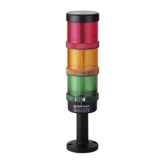
2. Technical information 2.1 Assembly 2.1.1 Terminal Element with USB interface (640.840.00) Description Quantity USB terminal element USB cable 1.8 m Software CD Instruction leaflet 2.1.2 Kompakt 71 with USB interface (697.430.53) Description Quantity Pre-assembled tower (red/yellow/green) with USB terminal element USB cable 1.8 m Software CD Instruction leaflet... -
Page 6: Safety Instructions
2.3 Safety instructions Caution! Please also refer to the instruction leaflet for your WERMA signal tower. The USB terminal element is not suitable for safety critical applications. For use with 24 V WERMA signal elements with max. 90 mA. KOMPAKT 71... -
Page 7: Technical Data
2.4 Technical data Operating voltage 5 V DC (USB) Output voltage 24 V DC (+/- 10 %) Current consumption Typ. 500 mA Output current Max. 90 mA Min. operating temperature - 25 °C Typ. operating temperature + 25 °C Max. operating temperature + 60 °C The signal tower elements can be triggered directly from a PC or Laptop via a standard USB interface. -
Page 8: Manual Driver Installation
4. Manual driver installation Note: Manual driver installation is only required if the USB terminal element is not recognised. Windows will open the following window. Close this window and open the Device Manager (Computer/Properties/Device Manager). Click with the right mouse button on USB TERMINAL ELEMENNT and then click on “Update Driver Software”. - Page 9 Select “Brows my computer for driver software” and insert the CD of the USB terminal element into your CD-ROM drive. Specify the location of the driver by clicking “Browse”. Select the “Driver” folder in the CD- ROM drive and confirm by clicking “Next”. Version 2.2 - 0514...
- Page 10 The driver for the USB terminal element has been successfully installed. Click “Close” to finish the update. Note: The USB terminal element is now ready for operation.
-
Page 11: Operation With Com Port
5. Operation with COM Port 5.1 Settings For the COM port you need the following settings: Baud rate 9600 bits per second Data bits Stop bit Parity None Flow control 5.2 Commands Note: Every command has to end with a return or line feed. 5.2.1 Version Type Command... -
Page 12: Write
5.2.3 Write Type Command Description Write WRXXXXX Sets the output, X could be: 0 Off 1 On 2 Blinking mode 1 3 Blinking mode 2 X Don’t care, no change on that tier WRXXXXX<CR> Return Tier 5 Tier 4 Tier 3... -
Page 13: Read
5.2.4 Read Type Command Description Read Information of current status. RD<CR> Return Information of status Example: RD<CR> 02131 (Tier 1: Off; Tier 2: Blinking mode 1; Tier 3: On; Tier 4: Blinking mode 2; Tier 5: On) 5.3 HyperTerminal Windows HyperTerminal or a comparable Linux application shows how the USB terminal element can be triggered. - Page 14 Now select the corresponding port (e.g. COM6) Set the bits per second in the following window to 9600 and flow control to none. Open the Properties File/Properties and the register Settings and press the button “ASCII Setup”.
- Page 15 Activate the line feeds and local echo Echo typed characters locally and confirm the window with OK. You can save these settings on your PC in order to retrieve them as required. Now you can pass the commands to the USB terminal element. Note the following points: - Make sure it is spelt correctly / correct case.
-
Page 16: Operation With Dynamic Link Library (Dll)
6. Operation with Dynamic Link Library (DLL) 6.1 Introduction The USB terminal element provides connectivity for a signal tower to the PC via USB. The user controls the USB module by using a specified dynamic link library (DLL) file found on the CD provided with the USB terminal element. -
Page 17: Basic Functions
Please note that these two functions cover the further functions (see next page). Further Functions Sets the status (ON or OFF) for all Outputs SetIOStatus Sets the status (ON, OFF, Blinking mode 1, Blinking mode 2) of a SetSingleIO single Output Gets the current Output status (ON or OFF) for all Outputs GetIOStatus Gets the status (ON, OFF, Blinking mode 1, Blinking mode 2) of a... -
Page 18: Getdevicestatus
Pos1, Pos2, Pos3, Pos4, Pos5 Sets port 1, 2, 3, 4 and 5 to OFF, ON, Blinking mode 1 or Blinking mode 2, depending on value. Macro Value As Char Value in ASCII Description 0x30 Port off 0x31 Port on Blinking mode 1 0x32 Blinking mode 1... -
Page 19: Getdeviceserial
6.3.2.4 GetDeviceSerial int GetDeviceSerial( [in] int DevIdx, [out] int * TypeCode, [out] int * BatchCode, [out] int * SerialCode) GetDeviceSerial gets the specified device serial code. This code is unique and can be use to distinguish between various devices currently installed in the system. Parameters DevIdx Index to the desire device currently available in the system. -
Page 20: Getfirmwareversion
6.3.2.6 GetFirmwareVersion int GetFirmwareVersion ( [in] int DevIdx, [out] int * Major, [out] int * Minor, [out] int * Build) GetFirmwareVersion gets the specified device firmware version. Parameters DevIdx Index to the desire device currently available in the system. The first index is 1. Major Pointer to a variable that will contain the device major firmware version value. -
Page 21: Further Functions
6.3.3 Further Functions Note: These functions are covered by the functions: SetDeviceStatus and GetDeviceStatus. 6.3.3.1 SetIOStatus int SetIOStatus( [in] int DevIdx, [in] int IOMask) SetIOStatus sets the status for all Outputs. Parameters DevIdx Index to the desire device currently available in the system. The first index is 1. IOMask Specifies the lights status mask of all the Outputs. -
Page 22: Getiostatus
Status Specifies the desire status for the given Output. 0 – OUTPUT OFF 1 – OUTPUT ON 2 – Blinking mode 1 3 – Blinking mode 2 Return Value 1 if successful, otherwise the return value is -1. 6.3.3.3 GetIOStatus int GetIOStatus( [in] int DevIdx, [out] int * OutMask) GetIOStatus gets the current Output status for all Outputs. -
Page 23: Getsingleio
6.3.3.4 GetSingleIO int GetSingleIO ( [in] int DevIdx, [in] int IOIdx, [out] int *Status) GetSingleIO gets the status of a specified single Output. Parameters DevIdx Index to the desire device currently available in the system. The first index is 1. IOIdx Specifies the index of current desire Output. -
Page 24: Usb Terminal Element Demo
7. USB Terminal Element Demo Start the Demo.exe, which is stored in the folder “Demo” on the CD. The following window opens. Note: Make sure that the Demo.exe and slma.dll or smla_x64.dll is stored in the same folder. Otherwise you will get an error message that the DLL was not found. Connect the USB terminal element to a USB port on your PC. - Page 25 WERMA Signaltechnik GmbH + Co.KG D-78604 Rietheim-Weilheim Fon: +49 (0)7424 / 9557-0 Fax: +49 (0)7424 / 9557-44 info@werma.com www.werma.com 310.640.008.0514...
Need help?
Do you have a question about the KombiSIGN 71 and is the answer not in the manual?
Questions and answers