Table of Contents
Advertisement
Quick Links
Advertisement
Table of Contents

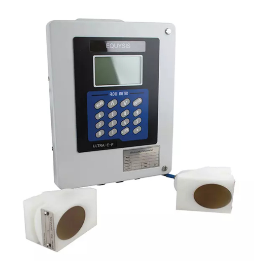
Summary of Contents for EQUYSIS ULTRA-E-F
- Page 1 ULTRA-E-F Transit Time Ultrasonic Flow Meter Clamp-on Manual...
-
Page 2: Table Of Contents
CONTENTS PART-1 INTRODUCTION ....................1 General ............................... 1 Principle of measurement........................1 Applications ............................2 Features .............................. 2 Specifications ............................. 3 Parts Identification ..........................4 PART-2 CLAMP-ON TRANSDUCER INSTALLATION ............ 6 General ............................... 6 Mounting Location ..........................6 Transducer Spacing ..........................7 Transducer Mounting ..........................8 Transducer Mounting Inspection and Couplant Application .............. - Page 3 PART-7 TROUBLESHOOTING AND FAQ ................38 Troubleshooting ............................ 38 Frequently Asked Questions and Answers ..................40 PART-8 WARRANTY AND SERVICE ................42 Warranty ............................... 42 Service ............................. 42 APPENDIX 1 INSERTION TRANSDUCER INSTALLATION ......... 43 A, Menu Configuration .......................... 43 B, Installation Locating ..........................
-
Page 4: Part-1 Introduction
Principle of measurement The ULTRA-E-F ultrasonic flow meter is designed to measure the fluid velocity of liquid within a closed pipe. The transducers are a non-invasive, clamp-on type, which will provide benefits of non-fouling operation and easy installation. -
Page 5: Applications
A pair of sensors can satisfy different materials , wide different pipe diameters Clear, user-friendly menu selections make ULTRA-E-F series simple and convenient to use 4 Lines display, can display total flow, flow rate, velocity and meter run status. Parallel operation of positive, negative and net flow totalizes. -
Page 6: Specifications
Shield cable, standard 6 meters, (opt) Lengths to 300 meters Cable distance M transducer: 40-1000mm pipe I.D; L transducer: 1000-4500mm; S&K Pipe size transducer: 20-50mm; Insertion transducer: 80-4500mm Pipe material All kind of steel and cast iron, PVC etc. ULTRA-E-F... -
Page 7: Parts Identification
Parts Identification Transmitters: Standard wall-mounted Transducers: Ex-proof type (ATEX) K transducer High temperature transducer S-Transducer M-Transducer L-Transducer M-Mounting Frame (V method and Z method) S-Mounting Frame (V method and Z method) Accessories: Stainless Steel Strap Flexible belts Couplant ULTRA-E-F... - Page 8 K mode transducers: Size 3/4", 1" 3/4", 1", 1-1/4" 1-1/4", 1-3/4", 2" ULTRA-E-F...
-
Page 9: Part-2 Clamp-On Transducer Installation
PART-2 CLAMP-ON TRANSDUCER INSTALLATION General The transducers that are utilized by the Series ULTRA-E-F contain piezoelectric crystals for transmitting and receiving ultrasound signals through walls of liquid piping systems. The transducers are relatively simple and straight-forward to install, but spacing and alignment of the transducers is critical to the system's accuracy and performance. -
Page 10: Transducer Spacing
Pipe Diameters (**) Transducer Spacing ULTRA-E-F transducers are clamped on the outside of a closed pipe at a specific distance from each other. The transducers can be mounted in V-mode where the sound transverses the pipe two times, W-mode where the sound transverses the pipe four times, or in Z-mode where the transducers are mounted on opposite sides of the pipe and the sound crosses the pipe once. -
Page 11: Transducer Mounting
ULTRA-E-F flow meter. This data only needs to be modified if it is known that a particular liquid data varies from the reference value. Refer to Part 3 of this manual for instructions on entering configuration data into the ULTRA-E-F flow meter via the meter keypad. - Page 12 Menu 90. V-Mode and W-Mode Installation 1. For ULTRA-E-F transducers, place a single bead of couplant, approximately 0.5 inch [15 mm] width, on the flat face of the transducer. See Figure 2.2. Generally, silicone-based grease is used as an acoustic couplant, but any grease-like substance that is rated not to “flow” at the temperature that the pipe may operate will be acceptable.
- Page 13 M25. Note that this method suits for normal Small, Std. M and Large transducer. For Magnetic transducers, the definition of transducer spacing is the distance between the two scale lines, just as showed bellow: ULTRA-E-F...
- Page 14 Fold the template in half, bisecting the circumference. See Figure 2.5. Crease the paper at the fold line. Mark the crease. Place a mark on the pipe where one of ULTRA-E-F...
- Page 15 Signal Strength is observed. Signal Strength of between 60 and 95 percent is acceptable. On certain pipes, a slight twist to the transducer may cause signal strength to rise to acceptable levels. 7. Secure the transducer with a stainless steel strap or other. ULTRA-E-F...
-
Page 16: Transducer Mounting Inspection And Couplant Application
Dow 112 for high temperature application. B, Transducers for High Temperature Mounting of high temperature transducers is similar to ULTRA-E-F standard transducers; High temperature installations require acoustic couplant Dow Corning 112 that is rated not to flow at the temperature that will be present on the pipe surface. -
Page 17: Part-3 Transmitter Installation And Operation Instructions
1 Locate the transmitter within the length of transducer cable that was supplied with the ULTRA-E-F system. If this is not possible, it is recommended that the cable be exchanged for one that is of proper length. Transducer cables that are up to 990 feet [300 meters] may be accommodated. -
Page 18: Transmitter Wirings
Guide the transducer terminations through the transmitter conduit hole located in the bottom-center of the enclosure. The terminals within ULTRA-E-F are a pluggable type - they can be removed wired and then plugged back in. Connect the appropriate wires to the corresponding screw terminals in the transmitter. -
Page 19: Keypad Configuration
Connect line power to the screw terminals N, L and GND in the transmitter. The ground terminal grounds the instrument, which is mandatory for safe operation. DC Power connection: The ULTRA-E-F may be operated by a 12-36 VDC source, which is capable of supplying a minimum of 3 Watts. -
Page 20: Part-4 Windows Display Explanations
ENTER key to confirm the to change the selection and wait until “1. selection. It is possible to press the key Stainless Steel” is displayed on the second line of the screen. Then press the ENTER key to confirm. ULTRA-E-F... - Page 21 & time, meter run status etc. 11 ~ 29 windows for initial Parameter Setup: To enter pipe outside diameter, pipe wall thickness, pipe material type, fluid type, transducer type, etc. For ULTRA-E-F, pipe material type selection is not necessary.
- Page 22 Transducers in Part 2). 9. Press the 1 keys to enter Window No.01 to display measurement result. MENU 10. Press the X keys to directly enter Window No.XX to display Mxx contents, MENU where X is digital number on keypad. ULTRA-E-F...
- Page 23 6. Polystyrene 7. Polyester. 8. Polyethylene 9. Ebonite 10. Teflon 11. Others Window for entering the liner thickness, if there is liner Window for selecting fluid type familiar liquids types include: 0. Water 1. Sea Water 2. Kerosene 3. Gasoline ULTRA-E-F...
- Page 24 60-70, user can enter Empty Pipe Setup value 50, and then meter will display 0 flow rate when Q value is less than 50. In good pipe status, please do not setup this value too small. Above is initial parameter setup (M11-M29) ULTRA-E-F...
- Page 25 The multiplier ranges from 0.001 to 10000, default value is ×1, addition, if select total flow pulse output, this value represent one pulse corresponding value. Turn on or turn off the NET Totalizer Turn on or turn off the Positive Totalizer Turn on or turn off the Negative Totalizer ULTRA-E-F...
- Page 26 Network environment Identification Number for PC communication system. System Lock, to avoid modification of the parameters. Unlock it only using the correct password. If forgot, contact factory for the password ULTRA-E-F...
- Page 27 Use key ∧ or ∨, can select 0. 4-20mA different mode: 4-20MA, 0-4-20MA, 0-20MA, 20-4-20MA etc. It is useful if negative flow occurs. For instance, select 0-4-20MA output; user can define 0-4MA as negative flow, 4-20MA as positive flow. ULTRA-E-F...
- Page 28 Press ENTER to change it if necessary. Above is service options and CL output applications Display Version information and Electronic Serial Number (ESN) that are unique for each series ULTRA-E-F flow meter. Communication setup: “115200, None”. Temperature range of inlet temperature sensor for heat flow application, wiring terminals is Tin+, Tin-.
- Page 29 The history logger of net totalizer net totalizer of day net totalizer of month net totalizer of year Auto. Correction Auto gain the totalizer flow if system power off Heat Flow Unit: kWh; GJ Temp. Selection: 0. From T1, T2 input ULTRA-E-F...
- Page 30 Calibrate T2 at 200℃ Note: Some contents in window menu order are not displayed in new software version, it won’t ∧ ∨ to scroll the menu window and view or setup influence user to use ULTRA-E-F, just press necessary menu contents. ULTRA-E-F...
-
Page 31: Part-5 Output Functions
Refer to Menu 53, 54, 55, 56, 57 and 58. Possessing a current loop output exceeding an accuracy of 0.1%, the ULTRA-E-F is programmable and configurable with multiple output modules such as 4 ~20mA or 0~20mA, selected in Window M54. For details, please refer to Part 4 –... -
Page 32: Relay Output
MODBUS-RTU Protocol Modbus Register Address Register Address Data Length Function (Expressed in Hex) Format 0000 IEEE754 Read Flow rate per day (m 0002 Floating Read Flow rate per hour (m Point 0004 Read Flow rate per minute (m ULTRA-E-F... - Page 33 Flow velocity 01 03 00 08 00 02 45 C9 Positive totalizer 01 03 00 0A 00 02 E4 09 Negative totalizer 01 03 00 0C 00 02 04 08 Net totalizer 01 03 00 0E 00 02 A5 C8 ULTRA-E-F...
-
Page 34: Data Storage Function
The Go On time means that the duration of logging data. If the Go On time is larger than 24 Hours, set the Go On time as Go On **:**:**. (“*” is input by the key .) M51 Logger Setup Date 12-01-14 Logger Options Start **:**:** Time 15:16:46 Intervl 00:00:05 Go On **:**:** ULTRA-E-F... - Page 35 Hour Month Save another file by naming rules when the “csv” file has recorded 2000 data. (Default: 2000, according to requirement, the number can change, please consult factory) When opening the “csv” file, the data are shown as below: ULTRA-E-F...
-
Page 36: Part-6 How To Use Menu Functions
Q value is short for Signal Quality (displayed in Window M90). It indicates the level of the signal detected. In the ULTRA-E-F, Q value is indicated by numbers from 00~99. 00 represents the minimum signal detected while 99 represent the maximum. Normally, the transducer position should be adjusted repeatedly and couplant application should be checked frequently until the signal quality detected is as strong as possible. -
Page 37: How To Judge Whether The Instrument Works Well On Site
1) Enter Menu 11, input the pipe outside diameter “38”; 2) Eenter Menu 12, input pipe wall thickness “4”; 3) Enter Menu 14, select pipe material “0. Carbon steel”; 4) Enter Menu 16, select liner material “0. No liner”; 5) Enter Menu 20, select fluid type “0. Water”; ULTRA-E-F... -
Page 38: How To Judge The Liquid Flowing Direction
6) Enter Menu 23, select transducer type “5. Plug-in B45”; 7) Enter Menu 24, select transducer-mounting method “1. Z-method”; 8) Enter Menu 01 to display measurement result. At this moment, the S and Q value should be 0 in Menu 01. 3. -
Page 39: How To Stabilize The Flow
2/1.98. This means that the scale factor is 1.01. The scale factor default is “1”or a factory calibration value (see the calibration data sheet for every meter) for each instrument prior to shipment from the factory. The scale factor entered ULTRA-E-F... -
Page 40: How To Do When All Keys Or Enter Key Is Invalid
Measurement units options, Metric or English, select M30, Press ENTER, and scroll the ∧or ∨ to select units; Flow rate units, Select M31, Press ENTER, and scroll the ∧or ∨ to select units. Details please refer to Part 4, Windows Display Explanations. ULTRA-E-F... -
Page 41: Part-7 Troubleshooting And Faq
Errors displayed in the ULTRA-E-F are divided into two categories: Table 1 is for errors displayed during self-diagnostics upon power on. “* F” may be displayed on the upper left corner of the screen after entering the measuring mode. - Page 42 * Check settings(refer to value No influence 120%. Window M66-M69)and normally. Ignore it if no * Improper settings to confirm if the actual flow frequency output is being frequency output or actual is too high. used. flow are too high. ULTRA-E-F...
-
Page 43: Frequently Asked Questions And Answers
Ensure that the value in M41 is smaller than the actual flow rate. Q: With a poor measurement site environment in the site and the voltage and power supplies fluctuating widely, is the instrument really able to keep running 24 hours a day repeatedly ULTRA-E-F... - Page 44 A: ULTRA-E-F is designed to work with high reliability under such conditions. It is provided with an intelligent signal conditioning circuit and internal correction circuitry. It will work under strong interference conditions and is able to adjust itself with strong or weak sound waves.
-
Page 45: Part-8 Warranty And Service
2) For other operational problems, please contact our local distributor by telephone, fax or email. In most cases, the problem could be solved immediately. ULTRA-E-F... -
Page 46: Appendix 1 Insertion Transducer Installation
24, Transducer Mounting is: 1. Z, for the Insertion transducer, pipe line diameter ≥80mm.) B, Installation Locating After entering the setup parameters, the ULTRA-E-F will calculate the transducer spacing in Menu 25. The transducer spacing is distance between the centre points of two insertion transducers. - Page 47 B, L = BC, L is transducer spacing in Menu 25. Fig.6 Remove the positioning paper, prepare weld the ball valve bases on A and B point, note that the center point of Ball Valve Base coincidences with the A, B points. ULTRA-E-F...
-
Page 48: E, How To Obtain Good Signal Strength And Signal Quality
Screw one transducer or another transducer, let the value of Menu 90 at least >60. The scale factor is used to modify the measurement results, factory default is 1.0 or other value depends on calibration. The user can enter a numerical value other than 1.0 according to re- calibration results. ULTRA-E-F... -
Page 49: Appendix 2 Energy Function Instruction
Menu 85 Temperature Signal Origin Selection 0. From T1, T2 input 1. Fixed temperature difference Menu 86 Select the specific heat according to international standard. Select >0. GB Menu 87 Open or Close energy flow totalizer. Menu 88 Totalizer multiplication factor selection ULTRA-E-F... -
Page 50: Temperature Range
6. Clamp-On Temperature Sensors Installation When determining the installation position of temperature sensor, we should pay attention to the pipeline surface. Pipeline surface must be clean before installing temperature sensor, then use belts to fix temperature sensor. ULTRA-E-F... -
Page 51: Appendix 3 Mounting Frame Installation
To fix bracket Copper and metal Screws chains To surround Metal Chains pipe and fix brackets To connect Latchs brackets and chains To fix copper Nuts screws To fix guide Combination rods and Screws graduated scale To fix Screws transducer ULTRA-E-F... -
Page 52: Installation Steps For V And W Transducer Mounting Methods
When finishing guide rods installation, it will be shown as the following picture. If measured pipe size is larger than 250mm, it should add guide robs with outside thread. The inside thread rob is connected to outside thread rob through thread. ULTRA-E-F... - Page 53 D, Fix the bracket on pipeline According to the pipe size, adjust the latch 2’s position on metal chain to make copper screw across the hole in the bracket, and ensure metal chain around pipeline and straight, shown as ULTRA-E-F...
- Page 54 100±3%, maybe need to adjust transducer mounting spacing a little) Equably spread couplant on measuring side of transducer, and then put transducer into bracket from broadside, make sure pipeline and transducer have good coupling. Use screws to fix transducers. Refer to the following pictures. ULTRA-E-F...
-
Page 55: Installation Steps For Z And N Transducer Mounting Methods
Refer to step C in steps for V and W method. Due to install the two transducers on the opposite sides of pipeline, do not use guide rods and graduated scale. B, Fix bracket to pipeline Refer to step D in steps for V and W method. Use latch and metal chain to fix bracket on ULTRA-E-F... - Page 56 Use screws to fix transducers. Refer to the following pictures. Notes: 1. Keep transducer end face and bracket end face at the same plane. 2. When use screw to fix transducer, we can observe the installation from broadside. ULTRA-E-F...
-
Page 57: S-Mounting Frame Installation
Guide Rod To fix brackets Retaining To retain Plates brackets To connect Stainless Steel bracket Screws retaining plate Combination To fix screws Nuts Combination To fix Screws transducers To fix guide Screws To fix Wing Nuts retaining plate ULTRA-E-F... -
Page 58: Installation Steps For V And W Transducer Mounting Methods
When fixing guide rod, we should pay attention to transducer mounting spacing. The spacing between two transducers should be the same as the value shown in Menu 25. In practical application, in order to keep signal quality Q (Menu 90) more than 60, and make ULTRA-E-F... -
Page 59: Installation Steps For Z And N Transducer Mounting Methods
Installation steps are as follow. A, Fix transducer in bracket Refer to step A in installation steps for V and W method. B, Install one transducer to pipe Equably spread couplant on measuring side of transducer, and then put the whole component ULTRA-E-F... - Page 60 C, Install the other transducer Based on the transducer mounting spacing(Menu 25), repeat steps A and B to install the other transducer. Notes: Do not over tighten to prevent couplant extrusion. ULTRA-E-F...
-
Page 61: Appendix 4 Fuild Characteristic (Sound Speed)
Glycol 1110 1658 5439.6 -2.1 Isobutanol 1212 3976.4 Iso-Butane 1219.8 4002 Isopentane 3215.2 -4.8 0.340 0.211 Isopropanol 1170 3838.6 2.718 2.134 Isopropyl alcohol 1170 3838.6 2.718 2.134 Kerosene 1324 4343.8 -3.6 Linalool 1400 4590.2 Linseed Oil 925-939 1770 5803.3 ULTRA-E-F... -
Page 62: Water Sound Speed
Units: Sound Speed: m/s Temperature Sound Temperature Sound Temperature Sound Temperature Sound ℃ ℃ ℃ ℃ Speed Speed Speed Speed 1402.3 1496.6 1542.5 1555.1 1407.3 1499.2 1543.5 1555.0 1412.2 1501.8 1544.6 1554.9 1416.9 1504.3 1545.5 1554.8 1421.6 1506.7 1546.4 1554.6 ULTRA-E-F... -
Page 63: Pipe Material Sound Speed Table
Glass 3276 Polyethylene 1600 Polyethylene 1950 PTFE 1450 2540 Rubber 1600 Equipos y Sistemas para Medir y Tratar Agua, S.A. de C.V. Matehuala No.109, Mitras Centro, Monterrey, Nuevo Leon, cp 64460 Phone: (81) 1970 8900 E-mail: ventas@equysis.com Web: www.equysis.com ULTRA-E-F...
Need help?
Do you have a question about the ULTRA-E-F and is the answer not in the manual?
Questions and answers