Advertisement
Quick Links
1
INTRODUCTION
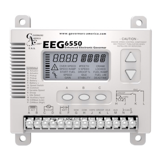
GAC's EEG6550 Series digital governor is designed to regulate engine
speed on diesel and gasoline reciprocating engines. With flexibility, pre-
cision, and accurate control of governed speed, the EEG is designed
for industrial engine applications from generator sets and mechanical
drives, to pumps or compressors.
The EEG6500 Series Quikset Display allows its operator to monitor and
configure parameters without needing configuration software or a PC.
◊
Improved, simple LCD User Interface
◊
Fast setup with 5 pushbuttons, no potentiometers
◊
Rated, Idle Speed, and Variable Speed
◊
Selectable Isochronous, Droop, & Variable Governing
◊
Built-In Fault Protection With Overcurrent Sensing
◊
Adjustable Starting Fuel Strategy (Black Smoke Reduction)
◊
Extended Speed Range to 12KHz or 6000 RPM with Frequency
Display
◊
Speed Ramping (Idle to Rated or any Speed Setting)
◊
Includes Standard GAC AUx Input for Synchronizing and Load
Sharing
◊
J1939 Engine Data and Speed Output
◊
Overspeed Sensing & Protection
◊
Compatible with all GAC actuators except ADB335 and ACB2001.
2
SPECIFICATIONS
Performance
Isochronous Operation
Speed Range / Governor
Idle Adjust
Droop Range
Speed Trim
InPUT / oUTPUT
Supply
Polarity
Power Consumption
Speed Sensor Signal
Actuator Current
Load Share/
Synchronizer Input
Reverse Power Protection
Transient Voltage Protection
EEG6550
Enhanced Electronic Governor
With Quikset Display
± 0.25 %
100 Hz - 12 KHz
(200-6000 RPM
w/120 tooth flywheel) cont.
Up to1500 RPM
1 - 25 % regulation
Programmable ±120 Hz
12-24 V DC Battery Systems
(6.0 to 32 V DC)
Negative Ground (Case isolated)
200 mA MAx continuous
plus actuator current
1.0 - 60.0 V RMS
8-10 Amps Continuous,
Momentary 12A MAx.
PWM output constant 500 Hz
0-10 V DC (5 V nominal,
reversed polarity, 145 Hz / V )
Ambient Temperature
Relative Humidity
All Surface Finishes
Dimension
Weight
Mounting
Vibration
Shock
Testing
comPlIance / STanDarDS
Agency
Communications
Yes
60 V
EEG6550 Enhanced Electronic Governor 5-2020-A1
1
Governors America Corp. © 2020 Copyright All Rights Reserved
envIronmenTal
-40° to 85 °C (-40 to 185 °F)
Fungus Proof and Corrosion Resistant
PHYSIcal
See Section 3 , Installation
1.8 lbf (820 gf)
Any position, Vertical Preferred
relIaBIlITY
7 g, 10-2000 Hz
100 % Functional Test
CE, (EN55011, EN50081-2
and EN50082-2)
SAE J1939 (Optional)
up to 90 %
20 g Peak
PIB1118
Advertisement

Subscribe to Our Youtube Channel
Summary of Contents for GAC EEG6550 Series
- Page 1 Enhanced Electronic Governor With Quikset Display INTRODUCTION GAC’s EEG6550 Series digital governor is designed to regulate engine speed on diesel and gasoline reciprocating engines. With flexibility, pre- cision, and accurate control of governed speed, the EEG is designed for industrial engine applications from generator sets and mechanical drives, to pumps or compressors.
-
Page 2: Installation
INSTALLATION Mount in a cabinet, engine en- closure, or sealed metal box. Vertical orientation allows for the draining of fluids in moist environments. Avoid Extreme Heat [mm] Dimensions: • Use an overspeed shutdown device, independent of the governor system, to prevent loss of engine control which may cause personal injury or equipment damage. - Page 3 WIRING Ground to Case Actuator Magnetic Speed Pickup Battery (12V or 24V) 0-2.5 v or 4-20 ma* varIaBle SPeeD InPUT 5K Ω reSISTIve SPeeD TrIm PoT Variable Speed / Trim 120 Ohms Potentiometer ( End of CAN bus) Ground to VSPD Case Droop...
-
Page 4: Display And Controls
DISPLAY & CONTROLS ParameTer UnITS ParameTer valUe Displays the value of a selected parameter or Displays the units for the parameter (e.g. RPM) live running parameter. This area will blink if a system shutdown and restart is required. SeconDarY ParameTerS Pressing UP or DOWN arrow toggles through the ParameTer aDjUST four secondary parameters: Engine Speed (RPM),... - Page 5 FEATURES TrIm or varIaBle SPeeD oPeraTIon Trim function - Performs finer adjustments (e.g. generator frequency) The resistive input speed function is active when the VSPD (Variable Speed) parameter is OFF (default value is OFF). 5K Ω potentiometer typical. variable Speed function - Operates over a larger RPM range. Variable speed 0 - 2.5 V input to Terminal J is active when VSPD (Variable Speed) parameter is ON.
- Page 6 When enabled, IDLE has an independent Gain adjustment. aUXIlIarY InPUT The Auxiliary (Aux) input, Terminal M, accepts signals from auto synchronizers, load sharing units, and other GAC acces- sories. Auxiliary Input Polarity (AUXP) set for InC: Increases Speed w/ Increased Voltage or dEC: Decreases Speed w/ In- creased Voltage.
- Page 7 FEATURES (CONTINUED) ServIce HoUr meTer SRVT sets the hour meter for an alert at the selected service interval. Range of adjustment is 1 to 2000 hours, the default value is 500 hours. If the service time is expired, the displayed number will be ‘0’ or negative. Disable SRVT by selecting OFF on the Advanced Menu parameter page.
- Page 8 PRE-START SET-UP & qUICkSET PARAMETERS Set the following parameters before starting the engine: #TeeTH Input the Number of Teeth on the Flywheel. This can not be changed while engine is running. cranK Input the Crank Termination (RPM) SPeeD Input the Fixed Speed of the Engine (RPM) aDjUSTaBle QUIKSeT ParameTerS over SPeeD * #TeeTH...
- Page 9 ADJUSTING FOR STABILITY Once the engine is running at operating speed and at no load, the following governor performance adjustments can be made to increase engine stability. GaIn - raTeD SPeeD & IDle SPeeD The EEG6500 is equipped with two separate gains, one for rated speed, the other for idle speed. Both are set using the GAIN setting on the Quikset Menu.
-
Page 10: Fault Codes
FLCU / NLCU Setting invalid Load calculation done with 0.5 & 4.0 amp values Adjust NLCU / FLCU For all other codes, note the condition and contact GAC. The WARNING indicator will blink and failures ImPorTanT will cause a system shut down. -
Page 11: System Troubleshooting
SYSTEM TROUBLESHOOTING SYSTEM TROUBLESHOOTING SYSTem InoPeraTIve If the engine governing system does not function, the fault may be determined by performing the voltage tests described in Steps 1 through 3. Positive (+) and negative (-) refer to meter polarity. Should normal values be indicated during troubleshooting steps, then the fault may be with the actuator or the wiring to the actuator. - Page 12 Check SPEED, IDLE, GAIN, START FUEL, and CRANK If unsuccessful in solving instability, contact GAC for assistance. GAC@governors-america.com or call: 1-413-233-1888 EEG6550 Enhanced Electronic Governor 5-2020-A1 PIB1118 Governors America Corp. © 2020 Copyright All Rights Reserved...
- Page 13 eeG6550 Technical assistance Worksheet Please provide the following information so we assist you with timely, technical recommendations: Date: Company Name: Contact Info: E-Mail Address: Phone Number: Reported Problem: Engine Make, Model & Application: Controller Model and Serial Number: Actuator Model and Serial Number: eeG6550 Governor SeTTInGS aDvanceD SeTTInGS Parameter...
Need help?
Do you have a question about the EEG6550 Series and is the answer not in the manual?
Questions and answers