Table of Contents
Advertisement
Advertisement
Table of Contents
Troubleshooting

Related Manuals for Flow HYPERJET 94i-S


Summary of Contents for Flow HYPERJET 94i-S
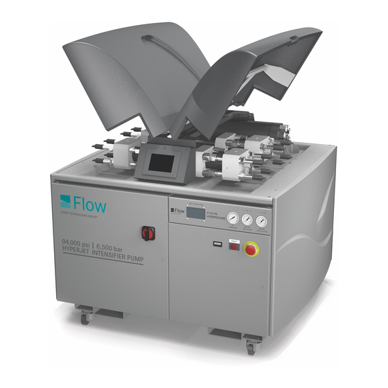
- Page 1 HYPERJET™ 94i-S & 94i-D M-390 | REV. C | APRIL 2010...
- Page 2 Due to continuing product improvement, the information contained in this document is subject to change without notice. Flow International Corporation shall not be held liable for technical or editorial omissions made herein, nor for any incidental or consequential damage resulting from the use of this material.
-
Page 3: Table Of Contents
Replacing a complete intensifier assembly 59 Configuration Screen 1 27 Intensifier shift module 60 Configuration Screen 2 27 Pilot valve 62 Configuration Screen 3 28 Shift valve 64 Configuring the clock 28 Defaults 29 Display Services 29 M-390 | 3 © Flow International Corporation... - Page 4 MS-2258, Maintenance Log Chapter 5. Parts Lists Pump drawings 69 Spares 70 Kits 70 Service kits 72 Tools 73 Label kits 73 Miscellaneous service parts 74 Chapter 6. Customer Support MS-2266, Customer Support 4 | M-390 © Flow International Corporation...
- Page 5 Introduction Introduction The information in this manual will help you become familiar with your new Flow International (FLOW) equipment. It was compiled from the most current information available at the time of publication and is intended to cover the most common configurations.
- Page 6 HYPERJET™ 94i-S AND 94i-D PUMPS Notes 6 | M-390 © Flow International Corporation...
-
Page 7: Chapter 1. Equipment Description
Controlled with FlowMaster® software • FlowSense®, an early warning system for critical • parts Available in two versions: a single-motor 50 hp • (HyperJet 94i-S) or dual-motor 100 hp (HyperJet 94i-D) HyperJet 94i-D M-390 | 7 © Flow International Corporation... -
Page 8: Specifications
Chapter 5. Dimensions HyperJet 94i-S ..54 in. x 40 in. x 45 in. HyperJet 94i-D ..57.4 in. x 55.3 in. x 44.1 in. -
Page 9: Water Requirements
Water flow rate port on the bulkhead. BLEED DOWN WATER The minimum inlet water flow rate must be equal to 1.5 times the maximum output flow rate. Cooling water (to heat exchanger) A heat exchanger regulates heat build-up in the hydraulic oil. -
Page 10: Water Interface Connections
HYPERJET™ 94i-S AND 94i-D PUMPS Water interface connections Please note the following: Making the interface connections Flow recommends that you install manual on/off Connect inlet water line to • FILTERED WATER IN • valves in the inlet water and cooling water lines. Lo-... -
Page 11: Pump Startup Sequence
CAUTION parts and serious bodily injury. Contact FLOW Do not try to tighten any loose or leaking connections or seek professional installation assistance. while the pump is operating or while the line is pressurized. -
Page 12: Operating An Integrated Hyperjet Pump
HYPERJET™ 94i-S AND 94i-D PUMPS Operating an integrated HyperJet pump All integrated Flow intensifier pumps are operated using The pump uses an electronic proportional control valve the FlowMaster software controller. See manual M-322, to automatically ramp up high-pressure water. The digi-... -
Page 13: Running The Hyperjet 94I-D On One Motor
6. If FlowMaster was running while you were making the changes to the OPCPump.ini file, you must close the program and restart it in order to activate the changes. 7. Follow the Pump startup sequence on page 11 to restart the pump. M-390 | 13 © Flow International Corporation... -
Page 14: Shipping Or Storing The Intensifier Pump
• intensifier. 6. Use a small pump to force clean antifreeze through the cooling water circuit. To ensure that the flow control valve is open, run the pump until the oil is at operating temperature. Otherwise, bypass the flow control valve. A drill-motor operated transfer pump is often adequate. -
Page 15: Chapter 2. Safety
Safety precautions Highlights an operating condition or service procedure that can lead to impaired system FLOW designed your high-pressure waterjet cutting operation or equipment damage. system and related equipment with safety in mind. Throughout the manual, safety precautions and warn- Note: Highlights an operating condition or service ings for specific operations are highlighted. -
Page 16: Safety Tips
Exceeding these limits may result in serious injury to personnel or damage to the equipment. Shield and bundle equipment hoses and cables so • they do not obstruct the operator’s freedom of movement. 16 | M-390 © Flow International Corporation... - Page 17 Follow the manufacturer’s recommendations for • servicing the equipment, and use only original manufacturer replacement parts. Follow the manufacturer’s system startup procedure • to ensure safe operation. Use care when lifting equipment covers during • operation. M-390 | 17 © Flow International Corporation...
-
Page 18: Protective Clothing
90 dBa for more than FLOW recommends that work-site safety personnel ap- 1 hour must wear suitable ear prove all safety equipment and clothing for everyone protection. Ear plugs and muffs working around waterjet equipment. -
Page 19: Emergency Medical Information
The card illustrated below can be purchased from Flow (A-8466). The tag or card should contain the following standard information:... - Page 20 HYPERJET™ 94i-S AND 94i-D PUMPS Notes 20 | M-390 © Flow International Corporation...
-
Page 21: Basics Of Pump Control
Analog Input Status • Pump Shutdowns • Pump Warnings • Configuration screens Configuration screen 1 • Configuration screen 2 • Configuration screen 3 • Configuring the clock • Defaults • Display Services • M-390 | 21 © Flow International Corporation... -
Page 22: Main Control Screens
Main control screens Start Screen Main Run Screen The Start Screen shows the Flow logo and a single button. From the Main Run Screen, you can start [I] and stop [O] the pump. The screen also shows the pump’s main... -
Page 23: Change Pressure Setpoints
If the terminal block input is On, then you cannot force it to low pressure. Navigation Touch the Setpoints button to continue to the • Boost Pump Control screen M-390 | 23 © Flow International Corporation... -
Page 24: Boost Pump Control
Note: The operator must block the bleed-down to drain so the water can flow through the high-pressure tubing, then open the bleed-down to drain when purging is finished so the pump can operate normally. -
Page 25: Pump Status Screens
[O] = disabled (default) • Once enabled, data from these inputs will also be displayed on this status screen. Navigation Touch the Main Run Screen button to return to the • Main Run screen. M-390 | 25 © Flow International Corporation... -
Page 26: Pump Shutdowns
• Main Run Screen Main Run Screen Touch the Warnings page button to continue to the Touch the Shutdown Page button to continue to the • • Pump Warnings screen Pump Shutdowns screen 26 | M-390 © Flow International Corporation... -
Page 27: Configuration Screens
ENTER Navigation Touch the Setpoints button to continue to • Configuration Screen 2 Touch the Defaults button to continue to the • Defaults screen M-390 | 27 © Flow International Corporation... -
Page 28: Configuration Screen 3
Navigation Navigation Touch the Main Run Screen button to return to the • Touch the Setpoints button to configure the clock • Main Run Screen 28 | M-390 © Flow International Corporation... -
Page 29: Defaults
(°F/psi or °C/Bar). Navigation Touch the Main Run Screen button to return to the • Main Run screen M-390 | 29 © Flow International Corporation... - Page 30 HYPERJET™ 94i-S AND 94i-D PUMPS Notes 30 | M-390 © Flow International Corporation...
-
Page 31: Chapter 4. Maintenance And Troubleshooting
Flow recommends that you keep detailed service Correctly lubricate new bearings before operation. • records to help you prepare a maintenance schedule that is compatible with your application and production requirements. -
Page 32: Hydraulic Oil
HyperJet 94i-D: 37 gal (140 L) viced high-pressure component, clear all personnel from the immediate area until system pressure has Filtration 6 microns, continuous flow been applied for three minutes and cycled on and Cooling Oil-to-water heat exchanger off at least three times. Increase pressure slowly, a Optimum oil temper- 105°F (40.5°C) -
Page 33: Inspection And Maintenance Schedule
CHAPTER 4 Maintenance & Troubleshooting Inspection & maintenance schedule Flow equipment has been designed for long service life. However, maximizing the life, safety, and efficiency of the equipment is dependent on daily inspections and regular maintenance. Periodic maintenance can take the form of regularly scheduled preventive maintenance, such as the items listed below. -
Page 34: Troubleshooting Tips
If you have questions about anything on the trouble- shooting tables, contact FLOW Technical Service. Troubleshooting tips The following tips have been helpful in isolating system Using the troubleshooting table malfunctions and in correcting problems quickly. -
Page 35: Troubleshooting The Intensifier Pump
Leaking auto bleed-down valve The valve is hot to the touch; rework or replace the valve. 3. Oil pressure and high-pressure water pressure are satisfactory, but water flow though the nozzle is low Flow restriction in the downstream 1. Inspect the high-pressure inline filter, if installed. - Page 36 Drain, thoroughly clean, and refill the hydraulic oil system (see Cleaning a contaminated hydraulic system). 10. Excessive pump noise and loss of oil pressure Insufficient inlet hydraulic oil flow Make sure the reservoir is full of oil. to the pump Air in oil Inspect suction lines for leaks.
- Page 37 Maintenance & Troubleshooting 13. Attenuator is leaking water between the main housing and end cap A leak in this location is not field repairable. Do not attempt to repair. Contact Flow Technical Service. 14. High-pressure tubing is leaking Excessive torsional movement or Re-torque the fitting to recommended torque values;...
-
Page 38: Troubleshooting The Pump Using Flowsense
Go to Run Machine and click on Advanced | FlowSense • diagnostic in the menu bar. This screen is shown below. In the Flow Sense dialog box that is displayed, locate the • X in the Fault column and highlight that row. -
Page 39: Warning And Shutdown Conditions
Inspect supply valves and hoses. ter supply interrupted 2. High hydraulic oil temperature (warning and shutdown) Incorrectly adjusted cooling circuit Adjust cooling water flow control valve on pump bulkhead. Faulty heat exchanger Inspect and replace heat exchanger. Damaged intensifier low-pressure Refer to manual M-376, Hyperpressure™... - Page 40 HYPERJET™ 94i-S AND 94i-D PUMPS Notes 40 | M-390 © Flow International Corporation...
-
Page 41: Chapter 5. Servicing The Pump
• guide and related service procedure(s). not leave a residue (such as Citra-safe or isopropyl alcohol). Flow recommends that you set up a dedi- Read and understand each service procedure before • cated solvent tank for these critical parts. Contami- starting any work. -
Page 42: Service Notes
HYPERJET™ 94i-S AND 94i-D PUMPS Service notes The following recommendations were provided by Flow customers and technicians. Following this advice can lead to lower repair costs, shorter repair times, and in- creased service life. Monitor water seepage from end cap weep holes. If •... -
Page 43: Servicing The Hydraulic System Hydraulic Oil Pump
Servicing the Pump Servicing the hydraulic system Hydraulic oil pump A hydraulic pump generates hydraulic flow to operate the intensifier. The pump is connected directly to an electric motor by a flexible coupling. The pump does not need routine maintenance. -
Page 44: Replacing The Hydraulic Pump
1. Shut down the system. CAUTION 2. Drain the reservoir. If replacing the hydraulic pump because a catastrophic hydraulic pump failure contaminated the hydraulic oil system, see Cleaning a contaminated oil system. 44 | M-390 © Flow International Corporation... - Page 45 15. Fill the hydraulic oil reservoir until oil is visible in the sight gauge (recommended oils are listed on page 6). CAUTION You must add oil to the reservoir hydraulic pump case before operating the pump or you will SEVERELY damage the system. M-390 | 45 © Flow International Corporation...
-
Page 46: Cleaning A Contaminated Hydraulic System
Note: Before installing a new heat exchanger, test it for leaks as described in Servicing the heat Reservoir exchanger. Drain the contaminated oil from the reservoir. • Remove the cover from the reservoir and completely • clean the interior. 46 | M-390 © Flow International Corporation... - Page 47 The pump can be returned to operation. After operating the pump with fresh oil for 10– 20 hours, drain the reservoir and refill with fresh hy- draulic oil. Replace the oil filter. M-390 | 47 © Flow International Corporation...
-
Page 48: Checking The Hydraulic Oil
If the oil has a burned color or smell, or if • there is debris in the oil sample, additional ser- vice work is required. See Servicing the hydrau- lic pump for more information. 48 | M-390 © Flow International Corporation... -
Page 49: Changing The Hydraulic Oil
CHAPTER 5 Servicing the Pump Changing the hydraulic oil HyperJet 94i-S reservoir This is the accepted procedure for changing hydraulic oil. Your oil supplier can tell you how to properly dis- pose of used hydraulic oil. Service steps WARNING Place the main electrical disconnect in the OFF position and bleed down all high-pressure lines. - Page 50 When all work is satisfactory, remove tools, parts, and rags from the pump and close the doors. Remove the Out of Service tag from the main electrical disconnect. 50 | M-390 © Flow International Corporation...
-
Page 51: Replacing The Kidney Loop Oil Filter
6. Clean out the bowl and the filter housing and insert a new element. 7. Lubricate the new element o-ring with clean hydrau- lic oil and install in the housing head. M-390 | 51 © Flow International Corporation... -
Page 52: Servicing The Heat Exchanger
(see Chapter 1 for a list of recommended oils). CAUTION You must add oil to the reservoir hydraulic pump case before operating the pump or you will SEVERELY damage the system. 52 | M-390 © Flow International Corporation... -
Page 53: Servicing The Bleed-Down Valve
* Lack of water pressure is more likely caused by high-pressure water pressure sensor from the valve high-pressure valve failure than by solenoid valve failure. body. 4. Remove the valve from the pump bracket and place it on a clean workbench. M-390 | 53 © Flow International Corporation... - Page 54 18. Push the back-up ring down until seated against the flat bottom of the port. 19. Install the high-pressure seat in the high-pressure body, applying Blue Lubricant to mating surfaces. Note: The seat is symmetrical and either face may be inserted first. 54 | M-390 © Flow International Corporation...
-
Page 55: Replacing The Booster Pump
CHAPTER 5 Servicing the Pump Replacing the booster pump HyperJet 94i-S booster pump Service steps WARNING Place the main electrical disconnect in the OFF position and bleed down all high-pressure lines. Place an Out of Service tag on the main electrical disconnect and lock it out. -
Page 56: Replacing The Filter Elements
7. Run the intensifier pump for 5 minutes at low pressure with the cutting nozzle open to purge any air from the system. Failure to do so could damage the high-pressure seals. 56 | M-390 © Flow International Corporation... - Page 57 CHAPTER 5 Servicing the Pump HyperJet 94i-S water filter HyperJet 94i-D water filter M-390 | 57 © Flow International Corporation...
-
Page 58: Servicing The Shift Valve Manifold Assembly
The shift valve directs the return Manifold body • flow of oil from the other end of the intensifier to the reservoir via the return port of the manifold at the same time. This section contains service procedures for these com- ponents. -
Page 59: Replacing A Complete Intensifier Assembly
Note: The intensifier assembly weighs 265 lb Remove tools, parts and rags from the pump unit. The (120 kg). pump unit is ready for operation. M-390 | 59 © Flow International Corporation... -
Page 60: Intensifier Shift Module
Right hand side shift sensor cable assemblies or in the shift module. If both shift sensor as- semblies are known to be working correctly, there is an internal fault in the module and it must be replaced. 60 | M-390 © Flow International Corporation... - Page 61 6. Shut the pump down. Remove the test shift sensors and re-connect the intensifier shift sensors to the shift module. If the module does not operate as described it may need replacing. M-390 | 61 © Flow International Corporation...
-
Page 62: Pilot Valve
Note: When working on the valves, drain the oil valve. from the reservoir into a clean container able to hold 37 gallons (140 L). 62 | M-390 © Flow International Corporation... - Page 63 The pump unit is ready for operation. Note: This service procedure introduces a small amount of air into the hydraulic system which will purge auto- matically on pump unit start-up. M-390 | 63 © Flow International Corporation...
-
Page 64: Shift Valve
6. Loosen the cap screws (4 screws with in. socket and two with in.) on the shift valve in -turn in- crements until all torque is removed. Remove the shift valve body from the manifold. 64 | M-390 © Flow International Corporation... - Page 65 11. Lubricate the end cap o-rings with Parker Super O Ring Lube and install in the end caps. Install the end caps on the shift valve body. Torque the cap screws to 30 ft-lb (40.7 N-m). M-390 | 65 © Flow International Corporation...
-
Page 66: Main System Relief Valve
If you have questions about the relief valve, contact FLOW Technical Service. 3. Use a 30 mm (or 1 -in.) socket and handle on the main body of the relief valve to unscrew it from the manifold. -
Page 67: Shift Sensor Assembly
Bottom left Left-hand shift sensor See Integrated shift module for a description of the module indicator LED sequence of operation. Bottom right Right-hand shift sensor M-390 | 67 © Flow International Corporation... -
Page 68: Replacing A Shift Sensor Assembly
7. Inspect the actuator bore in the end bell. It must be while checking for leaks. Remove tools, parts and polished and have no gouges, burrs, or other surface rags from the pump unit. The pump unit is ready for disruptions. operation. 68 | M-390 © Flow International Corporation... - Page 69 Drawings and part numbers can become obsolete as a part of Flow’s ongoing product improvement. If part numbers are replaced by new numbers, Flow Customer Service will inform you when you order new parts. The drawings listed below are either illustrated in this chapter, or provided on the CD-ROM.
-
Page 70: Spares
Check valve inlet repair kit 014885-1 Check valve outlet repair kit 013157-1 Low-pressure seal kit A-2185 Blue Lubricant 015084-1 Bleed-down valve repair kit A-1449 0.45 micron filter cartridge A-1555 1 micron filter cartridge 70 | M-390 © Flow International Corporation... -
Page 71: Kits
CHAPTER 6 Engineering Drawings 040207-1 Rev. A For the intensifier Hose kit for HyperJet 94i-S Pump Refer to manual M-376, 94K HyperJet™ Intensifier Qty Part # Description Kits A-0410-17 Hose assembly, ¼" ID x 17" 014884-1 Check valve inlet repair kit A-00230-40 Hose assembly, 40"... -
Page 72: Service Kits
HYPERJET™ 94i-S AND 94i-D PUMPS Service kits 015084-1 Bleed-down valve repair kit HyperJet 94i-S tubing kit Item Part # Description Item Part # Description 011746-1 Poppet 013345-4.3 straight tubing 011747-1 Seal 5, 17 013345-7.75 straight tubing 011748-1 Bearing 019421-6 3.5 x 3.5 elbow tube... -
Page 73: Tools
CHAPTER 6 Engineering Drawings Tools Label kits 040226-2 040521-1 Rev F Tool kit Label kit for HyperJet 94i-S Item Part # Description Qty Part # Description 014630-1 Plunger seal tool 001843-1 CE Caution label 014631-1 Seal guide tool 011980-22 Hot spot label... -
Page 74: Miscellaneous Service Parts
Parker Super O Ring Lube Use as a lubricant for all o-rings that come in contact with hydraulic oil. MS-2258 Intensifier Pump Maintenance and Service Log One copy is provided on the CD-ROM. 74 | M-390 © Flow International Corporation... - Page 75 CHAPTER 7 Customer Support MS-2266, Customer Support M-390 | 75 © Flow International Corporation...
- Page 76 HYPERJET™ 94i-S AND 94i-D PUMPS Notes 76 | M-390 © Flow International Corporation...
Need help?
Do you have a question about the HYPERJET 94i-S and is the answer not in the manual?
Questions and answers