Table of Contents
Advertisement
Quick Links
Advertisement
Table of Contents
Troubleshooting

Subscribe to Our Youtube Channel
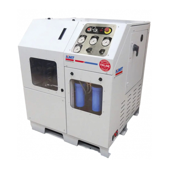
Summary of Contents for KTM TRILINE
- Page 1 TRILINE™ DIRECT DRIVE PUMP OPERATION AND MAINTENANCE MANUAL MANUAL 72183162(R01)
- Page 2 NOTICE This document contains subject matter in which KMT Waterjet Systems has proprietary rights. Recipients of this document shall not duplicate, use or disclose information contained herein, in whole or in part, for other than the purpose for which this manual was provided. KMT Waterjet believes the information described in this manual to be accurate and reliable.
-
Page 3: Table Of Contents
TABLE OF CONTENTS Title Page Notice Table of Contents Appendix Section Page 1 Introduction ......................1-1 Overview ....................1-1 Operational Overview ................1-2 Product Nameplate ................. 1-4 Intended Use of Equipment ..............1-4 Safety ..................... 1-5 Safety Precautions .................. 1-5 Training .................... - Page 4 3 Maintenance ......................3-1 Overview ....................3-1 Maintenance ................... 3-1 Daily Inspection ..................3-1 Periodic Maintenance................3-1 Mandatory Maintenance Schedule ............3-3 High Pressure System Maintenance............3-5 Maintenance Precautions ............... 3-5 4 Operation ........................ 4-1 Overview ....................4-1 Preparing the Pump for Startup.............. 4-2 Starting the Pump ...................
-
Page 5: Appendix
Low Pressure Filter Maintenance ............5-39 Servicing the Crankcase ................. 5-40 Lubricating the Pump ................5-40 Tensioning and Aligning the Belt Drive ..........5-40 Replacing the Belts ................5-43 5-10 Pressure Loading Tool Maintenance Kit ..........5-43 Bleeding the Pressure Loading Tool ............5-46 6 Troubleshooting ..................... -
Page 6: Introduction
SECTION 1 INTRODUCTION Overview The TRILINE™ direct drive pump is a powerful, high pressure waterjet cutting tool designed for minimum maintenance and reliable performance. Table 1-1 TRILINE™ Direct Drive Pump Motor Horsepower Maximum Single Rating Maximum Operating Orifice Diameter Motor... -
Page 7: Operational Overview
Section 1 Introduction Operational Overview Supply water is introduced through the 1/2-inch NPT connection on the bulkhead of the pump and is routed to the normally closed solenoid valve. When the pump is started, the solenoid valve opens and allows water to flow through the valve. The inlet water pressure is displayed on the pre-filter pressure gauge on the control panel. - Page 8 Section 1 Introduction Water pressure can be observed on the post-filter pressure gauge on the control panel. Water pressure is monitored by a 15 psi (1 bar) pressure switch on the low pressure manifold. If the pressure falls below 15 psi (1 bar) the red indicator light on the control panel will illuminate indicating low inlet water pressure.
-
Page 9: Product Nameplate
Figure 1-1: Product Nameplate Intended Use of Equipment The TRILINE™ pump has been designed solely for the generation of high pressure cutting water for industrial and commercial applications in non-explosive atmospheres, such as cutting parts from raw material on an x-y table. -
Page 10: Safety
Section 1 Introduction Safety The high pressure waterjet cutting system is a high energy cutting tool capable of cutting many dense or strong materials. Do not touch or be exposed to high pressure water. High pressure water will penetrate all parts of the human body. The liquid stream and the material ejected by the extreme pressure can result in severe injury. - Page 11 Section 1 Introduction Table 1-2 Safety Precautions The work area around the equipment shall be clean and free of debris and oil spills. To reduce the likelihood of slip, trip and fall hazards, it is the responsibility of the user of this equipment to clean up spills near the pump.
-
Page 12: Training
Section 1 Introduction Cautions emphasize operating or service procedures, or conditions that can result in equipment damage or impairment of system operation. Notes provide additional information that can expedite or improve operating or service procedures. Training All personnel operating, servicing or working near the waterjet cutting equipment shall adhere to all safety precautions described in this manual, as well as the applicable plant safety precautions. -
Page 13: Lockout/Tagout Procedure
Section 1 Introduction Lockout/Tagout Procedure This lockout/tagout procedure is designed to protect all employees from injuries caused by the unexpected energizing or startup of the machine, or the release of stored energy during service and maintenance. This is accomplished with energy isolating devices that prevent the transmission or release of energy. -
Page 14: Worldwide Product Support
Section 1 Introduction Worldwide Product Support The KMT Waterjet Customer Service Department is available to answer your questions regarding equipment installation and service. Technical assistance is available by phone and on-site support is available on request. On-site technical assistance is available during equipment installation and startup. Additionally, technical support for service and maintenance issues and training of operators and maintenance personnel is available. -
Page 15: Installation
SECTION 2 INSTALLATION Overview This section details equipment installation, and commissioning requirements and procedures. These procedures require a thorough understanding of the individual components and systems, safety issues, and the overall operation of the pump. All personnel involved in the installation, operation and/or service of the pump must carefully review this manual prior to installing and commissioning the machine. -
Page 16: Installation Requirements
Section 2 Installation Installation Requirements The pump must be installed indoors where air borne dust and contaminants are minimal. The ambient temperature should be between 45 F (7 C) and 104 F (40 C) to ensure proper operation of the pump. Water temperatures exceeding this range will result in seal life degradation. -
Page 17: Transporting
Section 2 Installation Figure 2-1: Equipment Dimensions Table 2-1 Equipment Dimensions Horsepower Length (A) Width (B) Height (C) Weight 41.0” (1041 mm) 50.0” (1270 mm) 30 HP 43.0” (1092 mm) 1125 lbs (510 Kg) Transporting The weight of the machine is not evenly distributed from one end to the other. The machine can be safely lifted from either end or either side. -
Page 18: Service Connections
Section 2 Installation Refer to the nameplate for machine specific ampacity and power voltage requirements. Service Connections The pump requires an incoming water source, a drain line, a high pressure discharge line and an air supply line. Thoroughly purge all supply plumbing prior to connection to remove any residue that could contaminate the system. -
Page 19: Inlet Water Requirements
Section 2 Installation Table 2-2 Service Connections Connection 1/2” NPT Supply water in HP cutting water out 3/8” HP 1/2” NPT Drain 1/4” NPT Air in Inlet Water Requirements The supply water must meet the minimum water quality standards outlined in Section 7, Specifications. -
Page 20: Plant Air
Section 2 Installation To ensure the pressure control valve does not suffer damage due to siphoned catcher tank water, connect the valve drain line directly to an outlet drain above the water line, or suspend the line above the catcher tank water level. Plant Air The facility compressed air connection should provide clean, dry air between 90 and 120 psi (6.2 and 8.3 bar). - Page 21 Section 2 Installation High pressure tubing and fittings must be rated for 60,000 psi (4,137 bar). Failure to use properly rated components may result in component failure causing equipment damage, personal injury or death. High pressure tubing lengths are coned and threaded prior to installation. KMT Waterjet provides both hand and power tools for coning and threading high pressure tubing.
-
Page 22: Measurements And Dimensions
Section 2 Installation Measurements and Dimensions Tubing must be cut to the proper length, both ends of the tubing must then be coned, threaded and deburred. To determine the tube length, measure the distance between the fittings, and add two times the engagement allowance shown in Table 2-5. -
Page 23: Power Coning
Section 2 Installation Power Coning 1. Secure the tubing in a tube vise. No more than the recommended length of tubing should extend beyond the face of the vice. See Table 2-7, Recommended Extension Length. 2. Mount the coning tool in a 3/8-inch or 1/2-inch, variable speed power drill. Apply cutting oil to the end of the tube and slide the coning tool on the tubing. -
Page 24: High Pressure Connections
Section 2 Installation Clean the machining chips from the die and body of the tool before threading the next tube. High Pressure Connections When installing high pressure discharge piping it is essential that all burrs are carefully removed and the tubing sections purged with clean compressed air prior to assembly. Lightly spraying the inside of the tube with a carrier fluid, such as WD-40, before purging with air will help carry the burrs. -
Page 25: Anti-Vibration Connections
Section 2 Installation Proper piping supports and guides must be provided. End connections will not support the tubing load alone. Anti-Vibration Connections The bending stresses resulting from excessive vibration or shock on the threaded area of the tubing can cause premature failure at the back of the thread. Anti-vibration connections must be used when tubing will be subjected to vibration, rotation and movement. -
Page 26: Commissioning
Section 2 Installation Commissioning When the machine has been positioned, all service connections installed, and the high pressure plumbing has been installed to the cutting area, the machine is ready to be commissioned. The following procedure is used for the initial startup and testing of the machine. 1. -
Page 27: Decommissioning
14. The pump is now ready for use. Decommissioning When the TRILINE™ pump is decommissioned and taken out of service for any reason all local regulations must be adhered to. All utilities must be de-energized and disconnected. All high pressure and low pressure water must be expelled from the pump if the pump is exposed to the potential of freezing temperatures. -
Page 28: Maintenance
SECTION 3 MAINTENANCE Overview Systems fail gradually; seals and connections begin to leak slowly or suddenly through specially designed weep holes. Water or oil dripping from a weep hole indicates internal seals or valves are beginning to fail, a warning that maintenance will be required. Maintenance In order to keep the equipment in optimum operating condition, routine and preventive maintenance is essential, see Table 3-1, Mandatory Maintenance Schedule. - Page 29 Section 3 Maintenance Use extreme care when aligning close tolerance parts for assembly. Do not force the parts together. If parts bind during assembly, they must be disassembled and realigned. Use only original KMT Waterjet replacement parts for consistent performance and reliability;...
-
Page 30: Mandatory Maintenance Schedule
Section 3 Maintenance Mandatory Maintenance Schedule Table 3-1 Mandatory Maintenance Schedule 3,000 Hours 500 Hours 1,000 Hours 1,500 Hours 2,000 Hours 2,500 Hours Major Kit 3,500 Hours 4,000 Hours 4,500 Hours 5,000 Hours Minor Kit Minor Kit Major Kit Minor Kit Minor Kit PCV Kit Minor Kit... - Page 31 Section 3 Maintenance Table 3-1 Mandatory Maintenance Schedule 3,000 Hours 500 Hours 1,000 Hours 1,500 Hours 2,000 Hours 2,500 Hours Major Kit 3,500 Hours 4,000 Hours 4,500 Hours 5,000 Hours Minor Kit Minor Kit Major Kit Minor Kit Minor Kit PCV Kit Minor Kit Minor Kit...
-
Page 32: High Pressure System Maintenance
Section 3 Maintenance High Pressure System Maintenance The high pressure system components are readily accessible, and can easily be removed from the unit for maintenance and service. High pressure fittings, valves and tubing must be rated for 60,000 psi (4,137 bar). Failure to use properly rated components may result in component failure, equipment damage and personal injury. - Page 33 Section 3 Maintenance Before performing any maintenance on the equipment, take the system out of service and make sure the controls are properly locked and marked. Never perform any maintenance on the equipment without making sure the main control power is locked out in the position.
-
Page 34: Operation
SECTION 4 OPERATION Overview The operator interface is through a manually adjustable display panel. Figure 4-1: Standard Display Table 4-1 Display Labels Inlet Water Pressure (pre-filter) Indicates water pressure before the inlet water has passed through the water filters Inlet Water Pressure (post-filter) Indicates water pressure after the inlet water has passed through both water filters High Air Pressure... -
Page 35: Preparing The Pump For Startup
Section 4 Operation Figure 4-2: Display with Optional Dual Pressure Control is changed from the local panel to remote controls using the keyed switch on the electrical enclosure. Preparing the Pump for Startup After initial installation Before the beginning of each shift ... -
Page 36: Starting The Pump
Section 4 Operation Never operate the pump without oil or with dirty oil. This can cause extensive damage to high pressure components. 3. Ensure water, air and drain lines are correctly routed and connected. The cutting head must be installed when operating the pump. 4. - Page 37 Section 4 Operation 5. Operate the pump at full pressure for 5-10 minutes while checking for leaks. If leaks are detected, stop the pump and observe the Lockout out/Tagout procedure before tightening any loose or leaking connections. Do not tighten any loose or leaking connections while the pump is operating or while the line is pressurized.
-
Page 38: Service Procedures
SECTION 5 SERVICE PROCEDURES Overview Procedures for installing mandatory maintenance kits as well as the replacement of worn parts that have reached the end of their life are included in this section. Follow the service guidelines listed below to achieve optimum performance and component life, ... -
Page 39: Service And Maintenance Overview
Section 5 Service Procedures Figure 5-1: High Pressure System Components Service and Maintenance Overview Never perform any type of maintenance on the pump while it is pressurized. Always turn the power off and bleed the high pressure water before servicing. Pressing the emergency stop button turns the control power off to the pump, and bleeds high pressure water through the drain. -
Page 40: Specialized Maintenance Tools
Section 5 Service Procedures Specialized Maintenance Tools Specialized tools have been designed to facilitate pump maintenance and are supplied with the pump. These tools, and their respective part numbers are listed in Table 5-1, Specialized Maintenance Tools. Table 5-1 Specialized Maintenance Tools Kit 72185375 Plunger nut tool 72185393... -
Page 41: High And Low Pressure Connections
Section 5 Service Procedures High and Low Pressure Connections Before performing any maintenance on the high pressure components, it is necessary to remove the high and low pressure water piping and air connection. Use the following procedure to remove and install the piping. Severe injury can result if the machine is not properly locked out. -
Page 42: Loading And Unloading The Tie Rods
Section 5 Service Procedures If maintenance will require removing the subplate, remove the cooling water connections on the subplate. 5. When the required maintenance has been completed and the components reassembled, install the high pressure tubing and anti-vibration connections from the end caps to the high pressure manifold. -
Page 43: Unloading The Tie Rods
Section 5 Service Procedures Do not attempt to tighten the tie rod nuts using a torque wrench. No other methods than those described in this section may be used to load the tie rods. Unloading the Tie Rods 1. Ensure the loading tool is clean and free of leaks or damage. 2. - Page 44 Section 5 Service Procedures 5. Tighten the tool studs firmly to seat the tool piston fully into the tool cylinder and against the end cap. Do not use any type of impact tool. 6. Verify the tool plunger is seated firmly against the stop. The tool plunger must be seated against the stop in order to fully seat the tool piston within the tool cylinder.
-
Page 45: Loading The Tie Rods
Section 5 Service Procedures 10. Use the 3/4-inch (19 mm) socket and ratchet to rotate the tool plunger counter-clockwise until the pressure is relieved and the gauge reads 0 psi (0 bar). Continue to rotate the plunger until it is fully retracted and against the stop. 11. - Page 46 Section 5 Service Procedures Figure 5-4: Loading the Tie Rods 6. While supporting the tool, hand-tighten the tool studs to thread the tool onto the end of the tie rods. Alternate between opposite studs to bring the tool in evenly and prevent binding. 7.
- Page 47 Section 5 Service Procedures 11. Use the 3/4-inch (19 mm) socket and ratchet to rotate the tool plunger counter-clockwise until the pressure is relieved and the gauge reads 0 psi (0 bar). Continue to rotate the plunger until it is fully retracted and against the stop. 12.
-
Page 48: Minor Maintenance Kit
Section 5 Service Procedures Minor Maintenance Kit The minor maintenance kit must be installed every 500 hours. Use the following procedure to install the minor maintenance kit. The minor maintenance kit contains the following replacement components. Table 5-3 Minor Maintenance Kit 72185099 Part Number Component... - Page 49 Section 5 Service Procedures Figure 5-5: Minor Maintenance Kit Read the entire procedure before beginning service, paying particular attention to safety instructions. All parts of the kit should be installed at the same time. Do not replace components individually.
- Page 50 Section 5 Service Procedures Severe injury can result if the machine is not properly locked out. Observe electrical Lockout/Tagout procedures before performing maintenance. Ensure all pressure is relieved or blocked from the high pressure circuits before performing maintenance. 2. Disconnect all high and low pressure connections, following the procedure, High and Low Pressure Connections.
- Page 51 Section 5 Service Procedures Use care when removing the dynamic seal and rod seal. Do not scratch or nick the seal carrier bore. 8. Remove the subplate adapter. If necessary, use pry bars or screwdrivers to remove the adapter. 9. Remove the retaining ring from the adapter using snap ring pliers.
-
Page 52: Lapping The Discharge Check Valve Body
Section 5 Service Procedures To prevent metal from being introduced into the openings on the outer circumference of the check valve body, do not cover the holes with the rebuild clamp. 17. Loosen and remove the cage. 18. Remove the compression spring, discharge poppet guide, discharge poppet and discharge poppet seat. -
Page 53: Discharge Check Valve Assembly Installation
Section 5 Service Procedures Discharge Check Valve Assembly Installation 1. Insert the new discharge poppet into the new poppet guide. Install the poppet into the guide with the back radius of the poppet going in first. The counterbore in the discharge poppet is visible after installation. 2. -
Page 54: Plunger Torque Verification
Section 5 Service Procedures Plunger Torque Verification 1. Carefully slide the plunger nut tool over the plunger and plunger nut. Torque the plunger nut to 20 ft-lbs (27 Nm). 2. Rotate the pulley to fully extend the next plunger to be checked. 3. - Page 55 Section 5 Service Procedures 3. Install the new rod seal with the v-shaped groove facing away from the carrier. 4. Install the new dynamic seal into the inner diameter of the rod seal, making sure the dynamic seal is fully seated against the carrier.
-
Page 56: High Pressure Cylinder Installation
Section 5 Service Procedures High Pressure Cylinder Installation 1. Lubricate the new o-ring with FML-2 grease and position it in the groove in the high pressure cylinder. 2. Slide the high pressure cylinder over the plunger and seat it against the dynamic seal carrier. Position the cylinder with the weep hole facing down. -
Page 57: End Cap Installation
Section 5 Service Procedures Figure 5-9: Inlet Check Valve Assembly Installation The sleeve helps align the poppet with the discharge check valve body and prevents pinching of the inlet poppet between the discharge check valve and the filler tube during installation. 7. -
Page 58: Pressure Control Valve Maintenance
Section 5 Service Procedures 1. Ensure all eight of the split bearings are in position in the end cap. 2. Align the end cap so it will slide over the tie rods, then carefully slide the end cap toward the crankcase until the discharge check valve makes contact with the inlet poppet. - Page 59 Section 5 Service Procedures Needle nose pliers may be required to remove the poppet from the assembly. 5. Lubricate the o-rings on the valve body with FML-2 grease and slide the adapter onto the valve body. 6. Install the new static seal ring on the new seat and loosely install the new poppet into the seat.
-
Page 60: Major Maintenance Kit
Section 5 Service Procedures Major Maintenance Kit The major maintenance kit must be installed every 1,500 hours. Use the following procedure to install the major maintenance kit. The major maintenance kit contains the following replacement components. Table 5-4 Major Maintenance Kit 72185284 Part Number Component... - Page 61 Section 5 Service Procedures Figure 5-11: Major Maintenance Kit Read the entire procedure before beginning service, paying particular attention to safety instructions. All parts of the kit should be installed at the same time. Do not replace components individually.
- Page 62 Section 5 Service Procedures Severe injury can result if the machine is not properly locked out. Observe electrical Lockout/Tagout procedures before performing maintenance. Ensure all pressure is relieved or blocked from the high pressure circuits before performing maintenance. 2. Disconnect all high and low pressure connections, following the procedure, High and Low Pressure Connections.
- Page 63 Section 5 Service Procedures Use care when removing the dynamic seal and rod seal. Do not scratch or nick the seal carrier bore. 7. Remove the subplate adapter. If necessary, use pry bars or screwdrivers to remove the adapter. 8. Remove the retaining ring from the adapter using snap ring pliers.
-
Page 64: Discharge Check Valve Assembly Installation
Section 5 Service Procedures To prevent metal from being introduced into the openings on the outer circumference of the check valve body, do not cover the holes with the rebuild clamp. 16. Loosen and remove the cage. 17. Remove the compression spring, discharge poppet guide, discharge poppet and discharge poppet seat. -
Page 65: End Cap Assembly
Section 5 Service Procedures End Cap Assembly 1. Lightly lubricate the new check valve o-ring with FML-2 grease and install it into the groove on the new check valve body. 2. Remove and discard the existing o-ring in the inner diameter of the end cap. -
Page 66: Subplate Adapter Installation
Section 5 Service Procedures 8. Repeat these steps for the remaining positions. 9. When finished, clean any dirt or grease from all of the plungers. Subplate Adapter Installation 1. Ensure the tie rods are firmly seated in the subplate. 2. Clean the cooling water holes in the adapter. 3. -
Page 67: High Pressure Cylinder Installation
Section 5 Service Procedures Ensure the plungers are clean and free of any scratches or damage before installing the dynamic seal carrier. The subplate adapter/seal carrier interface must be clean and free of debris. 5. Slide the dynamic seal carrier onto the plunger until the carrier is seated against the register of the subplate adapter. -
Page 68: Inlet Check Valve Assembly Installation
Section 5 Service Procedures A small amount of force may be required to seat the cylinder against the seal carrier. Inlet Check Valve Assembly Installation 1. Position the new inlet poppet spring over the shouldered side of the new inlet poppet. 2. -
Page 69: End Cap Installation
Section 5 Service Procedures 7. Insert the inlet check valve assembly, spring end first, into the high pressure cylinder, making sure to engage the spring into the dynamic seal. 8. Repeat this procedure for the remaining inlet check valve assemblies. End Cap Installation The end cap must be installed in one fluid motion toward the crankcase. - Page 70 Section 5 Service Procedures Figure 5-16: Pressure Control Valve Maintenance 4. Remove and discard the poppet, seat and static seal ring from the valve body. 5. Remove the valve adapter from the valve body. Needle nose pliers may be required to remove the poppet from the assembly. 6.
-
Page 71: Replacing The Belts
Section 5 Service Procedures 12. Remove the plug, from the crankcase drain and completely drain the oil. 13. Reinstall the plug, and fill the crankcase with oil to the level indicated on the dipstick. The crankcase oil is replaced every 500 hours as part of the mandatory maintenance schedule. -
Page 72: Pressure Control Valve Maintenance Kit
Section 5 Service Procedures Replace all four belts at the same time to maintain consistent performance of the drive system. 5. Turn the nut on the tension bar clockwise until there is tension on the belts. 6. Adjust the belt tension following the procedure, Tensioning and Aligning the Belt Drive. 7. - Page 73 Section 5 Service Procedures Figure 5-18: Pressure Control Valve Maintenance Kit Read the entire procedure before beginning service, paying particular attention to safety instructions. All parts of the kit should be installed at the same time. Do not replace components individually.
- Page 74 Section 5 Service Procedures 2. Reduce the air pressure to 0 psi (0 bar), and remove the air and drain lines from the pressure control valve. 3. Remove the high pressure manifold from the pump and place in a soft jawed vise. 4.
- Page 75 Section 5 Service Procedures Figure 5-20: Pressure Control Valve Maintenance Kit 9. Remove and discard the plunger. 10. Using the bearing removal/installation tool (P/N 72185492), push the bearing assembly from the bore of the valve body. Discard the bearing assembly. 11.
-
Page 76: Low Pressure Filter Maintenance
Section 5 Service Procedures 22. Position the poppet and seat assembly into the end of the valve body. 23. Lubricate the threads on the valve body with Pure Goop and thread the pressure control valve assembly into the high pressure manifold. Torque the valve body to 190 ft-lbs (258 Nm). -
Page 77: Servicing The Crankcase
Section 5 Service Procedures 6. Clean the housings and install new filter elements. 7. Use the strap wrench to install the housings on the filter heads. 8. Turn the supply water on and check for leaks. The supply water must be on before starting the pump. Failure to do so could severely damage the pump. - Page 78 Section 5 Service Procedures Check tension on a new drive belt frequently during the first day of operation and periodically thereafter. Excessive tension shortens belt and bearing life. Keep the belt and pulleys free from oil, grease, cutting lubricants or belt dressing. Any of these can cause the belt to slip.
- Page 79 Section 5 Service Procedures 3. Verify the indicator arm is positioned completely down and place your index finger in the finger strap on top of the click pad. 4. Press down slowly until it pad clicks. Immediately stop pressing and carefully remove the gauge.
-
Page 80: Replacing The Belts
Section 5 Service Procedures Replacing the Belts Replace the belts every 1,500 hours. Replace the belts sooner if they can no longer be tensioned properly. 1. Shut the system down and remove the belt guard. 2. Loosen the four, flanged nuts mounting the transmission housing to the electric motor. 3. - Page 81 Section 5 Service Procedures 1. Using two 7/8-inch combination wenches, loosen and remove the four cap nuts and remove the four tie rod extensions. 2. Remove the fill plug from the piston and drain the transmission fluid. Discard the used transmission fluid.
- Page 82 Section 5 Service Procedures 7. Loosen the left hand threads on the plunger adapter and remove the adapter from the tool cap. 8. Remove the plunger from the plunger adapter. 9. Place the tool cap on a workbench with the seal bore facing up. 10.
-
Page 83: Bleeding The Pressure Loading Tool
Section 5 Service Procedures 25. Apply FML-2 food grade grease to the backup ring and the o-ring. Insert the piston in the bore until it is fully seated. 26. Unseat the piston approximately 1/8-inch. This will allow the tool to be slightly overfilled with fluid to aid in evacuating all remaining air from the tool. - Page 84 Section 5 Service Procedures 5. Use a 14 mm combination wrench to loosen the gauge hex nut and bleed off pressure. Bleed excess pressure from the gauge weep port until the gauge reads zero bar. Tighten the hex nut. 6. Continue tightening the tool studs until the tool body or the tool studs bottom out against the tie rods and there is no further increase in gauge pressure when tightening the tool studs.
-
Page 85: Troubleshooting
To supplement the troubleshooting guide, refer to the troubleshooting illustration at the end of this section. The following symptoms are discussed in this section: Table 6-1: TRILINE™ Troubleshooting Guide Pump is leaking oil Pump is leaking water... -
Page 86: Troubleshooting Guide
If the symptoms in the guide do not correspond to the malfunction, or if the problem is not resolved by the recommended corrective action, contact the KMT Customer Service Department for assistance. Table 6-1 TRILINE™ Troubleshooting Guide Malfunction Indication Comments... - Page 87 Section 6 Troubleshooting Table 6-1 TRILINE™ Troubleshooting Guide Malfunction Indication Comments Pump is vibrating and/or Missing or worn anti- Install the pump on an anti- making noise vibration mat vibration mat. Replace the existing anti- vibration mat. Improper belt tension or Properly adjust the belt tension.
- Page 88 Section 6 Troubleshooting Table 6-1 TRILINE™ Troubleshooting Guide Malfunction Indication Comments Pump starts, but Shaft spins slowly or not at Replace the crankcase. immediately shuts down Motor overload shutdown has Identify the source of the been tripped overload and remedy the problem.
- Page 89 Section 6 Troubleshooting Table 6-1 TRILINE™ Troubleshooting Guide Malfunction Indication Comments Pump is running too hot Failed inlet check valve Install a Minor Maintenance Kit. See Section 5. Failed discharge check valve Install a Minor Maintenance Kit. See Section 5.
- Page 90 Section 6 Troubleshooting Table 6-1 TRILINE™ Troubleshooting Guide Malfunction Indication Comments Pump does not produce the Belts are slipping or have Replace the belts; see Section 5, desired pressure failed (broken or stretched) Replacing the Belts. Check belt tension and adjust as...
- Page 91 Section 6 Troubleshooting Table 6-1 TRILINE™ Troubleshooting Guide Malfunction Indication Comments Pump does not produce the Failed dynamic seal Inspect plunger and dynamic desired pressure, continued seal carrier to determine if May be an indication of a repairs require a Minor or a failed plunger, improper tie Major Maintenance Kit.
- Page 92 Section 6 Troubleshooting Table 6-1 TRILINE™ Troubleshooting Guide Malfunction Indication Comments Pump does not produce the Damaged low pressure water Inspect hoses and fittings and desired pressure, continued hose or loose fittings replace as necessary. Improper pulley ratio for Verify required pulley size for power frequency input power.
-
Page 93: Short Component Life
Section 6 Troubleshooting Short Component Life Ensure all recommended service and maintenance procedures Install all kit components at the same time, do not replace components individually Verify all utility and pump installation requirements have been met Common causes for excessively short component life include: ... - Page 94 Section 6 Troubleshooting Table 6-2 Short Component Life Guide Malfunction Indication Comments Inlet check valve Pinched inlet poppet Install a Minor Maintenance Kit. Broken compression spring Install a Minor Maintenance Kit. Worn filler tube or sleeve Install a Minor Maintenance Kit.
-
Page 95: Troubleshooting Illustration
Section 6 Troubleshooting Troubleshooting Illustration TEMPERATURE INCREASE Failed dynamic seal or discharge check valve COLD WATER Failed rod seal,failed or pinched subplate adapter o-ring HOT WATER Failed or loose static seal ring, WARM WATER failed manifold Catastrophic failure of dynamic seal HOT WATER HOT WATER Failed dynamic seal... -
Page 96: Specifications
SECTION 7 SPECIFICATIONS Overview Comprehensive listing of specifications for the TRILINE™ pump are provided in this section. Table 7-1 TRILINE™ Motor Horsepower Maximum Single Rating Maximum Operating Orifice Diameter Motor Pressure Water Volume (at full pressure) Speed 0.012” (0.30 mm) 55,000 psi (3,792 bar)* 0.84 gpm (3.18 L/min) -
Page 97: Pump Specifications
Section 7 Specifications Pump Specifications Minimum inlet water flow rate and pressure 2.0 gpm @ 57 psi (7.5 L/min @ 3.9 bar) Systems should be sized for 150% of the pump capacity Low inlet water pressure switch threshold 15 psi (1 bar) Required inlet water temperature range 55º-70º... -
Page 98: Water Quality Standards
Section 7 Specifications Table 7-2 ISO Air Quality Classifications Maximum Maximum Pressure ISO Quality Particle Size Dew Point Maximum Oil Content Class (microns) (water @ 100 psi) (Mg/m +45° F (+7° C) +50° F (+10° C) Water Quality Standards The quality of the inlet cutting water supply is one of the most important factors affecting component life and performance. - Page 99 Section 7 Specifications Table 11-1 Water Quality Standards Constituent Minimum (mg/l or ppm) Requirement Better Best Total Hardness 6.5-8.5 6.5-8.5 6.5-8.5 Turbidity (NTU) * Note: Total dissolved solids **Note: Do not reduce the TDS beyond this amount or the water will be too aggressive. Table 11-2 Water Impurities Constituent...
- Page 100 Section 7 Specifications Table 11-2 Water Impurities Constituent Chemical Formula Comments Sulfate Adds to solid content; combines with calcium to form calcium sulfate scale. Measure of the total amount of dissolved matter in water. Total Hardness CaCO Sum of all hardness constituents in water; typically expressed as their equivalent concentration of calcium carbonate;...
- Page 101 Overview This section contains a comprehensive list of all replacement parts and maintenance tools for the TRILINE™ direct drive pump. To facilitate the ordering of replacement parts, item numbers in each table correspond to the identifying numbers in the accompanying figures.
-
Page 102: Parts List
Section 8 Parts List Index Part lists are arranged in the following sequence: Parts List Index Part Part Table Description Number Page Table Description Number Page Minor Maintenance Kit 72185099 Pressure Loading Tool 72185434 8-10 Major Maintenance Kit 72185284 Spare Parts Kit 72185442 8-10 Poppet/Seat Assembly... - Page 103 Section 8 Parts List Table 8-1 Minor Maintenance Kit 72185099 Part Part Item Number Description Quantity Item Number Description Quantity 72185177 Dynamic Seal 204334082 O-Ring 72185125 Rod Seal 05122007 O-Ring 72185133 Inlet Poppet 20434082 O-Ring 72185141 Compression Spring 10074383 O-Ring 72185149 Sleeve 72185208...
- Page 104 Section 8 Parts List Figure 8-1: Minor Maintenance Kit 72183245 8-2016/Rev 01 ORIGINAL INSTRUCTIONS...
- Page 105 Section 8 Parts List Table 8-2 Major Maintenance Kit 72185284 Part Part Item Number Description Quantity Item Number Description Quantity 72185117 Dynamic Seal 204334082 O-Ring 72185125 Rod Seal 72185325 High Pressure Cylinder 72185291 Seal Carrier Assembly 05122007 O-Ring 72185133 Inlet Poppet 20434082 O-Ring 72185141...
- Page 106 Section 8 Parts List Figure 8-2: Major Maintenance Kit 72183245 8-2016/Rev 01 ORIGINAL INSTRUCTIONS...
- Page 107 Section 8 Parts List Table 8-3 Poppet/Seat Assembly, Pressure Control Valve 72185234 Part Item Number Description Quantity 72185250 Poppet Figure 8-3: Poppet/Seat Assembly 72185258 Seat 72185276 Static Seal Ring 72183245 8-2016/Rev 01 ORIGINAL INSTRUCTIONS...
- Page 108 Section 8 Parts List Table 8-4 Pressure Control Valve Maintenance Kit 72185333 Part Item Number Description Quantity 72185341 Bearing Assembly Figure 8-5: Pressure Control Valve Maintenance Kit 72185349 Plunger 72185357 Plunger Seal 10113884 O-Ring 72129276 O-Ring 72129268 O-Ring 10087385 FML-2 Food Grade Grease 72183245 8-2016/Rev 01 ORIGINAL INSTRUCTIONS...
- Page 109 Section 8 Parts List Table 8-5 Pressure Loading Tool 72185434 Part Item Number Description Quantity 72185434 Pressure Loading Tool Figure 8-6: Spare Parts Kit 72185442 Spare Pats Kit 72185450 Backup Ring, Oil Seal 72185458 Oil Seal 10074813 O-Ring 20434082 O-Ring 72185466 Backup Ring 20487868...
- Page 110 Section 8 Parts List Table 8-6 Tools Kits and Miscellaneous Part Item Number Description Quantity 72185375 Pump Tool Kit 72185393 Plunger Nut Tool 72185400 Rebuild Clamp 72185408 Belt Tensioner Gauge 10149052 Glass Pane 10084440 Pure Goop 05048681 Medical Alert Card 49881485 Hex Head Screw 95277109...
- Page 111 This document contains confidential and trade secret infor- ALL DIMENSIONS ALL DIAMETERS ON mation, is the property of KMT Waterjet Systems, and is KMT Triline pump IN INCHES [mm] COMMON CENTERLINE given to the receiver in confidence. The receiver by recep- COAXIAL TO .005...
- Page 112 This document contains confidential and trade secret infor- ALL DIMENSIONS ALL DIAMETERS ON mation, is the property of KMT Waterjet Systems, and is KMT Triline pump IN INCHES [mm] COMMON CENTERLINE given to the receiver in confidence. The receiver by recep- COAXIAL TO .005...
- Page 113 This document contains confidential and trade secret infor- ALL DIMENSIONS ALL DIAMETERS ON mation, is the property of KMT Waterjet Systems, and is KMT Triline pump IN INCHES [mm] COMMON CENTERLINE given to the receiver in confidence. The receiver by recep- COAXIAL TO .005...
- Page 114 This document contains confidential and trade secret infor- ALL DIMENSIONS ALL DIAMETERS ON mation, is the property of KMT Waterjet Systems, and is KMT Triline pump IN INCHES [mm] COMMON CENTERLINE given to the receiver in confidence. The receiver by recep- COAXIAL TO .005...
- Page 115 This document contains confidential and trade secret infor- ALL DIMENSIONS ALL DIAMETERS ON mation, is the property of KMT Waterjet Systems, and is KMT Triline pump IN INCHES [mm] COMMON CENTERLINE given to the receiver in confidence. The receiver by recep- COAXIAL TO .005...
- Page 116 MATERIAL SAFETY DATA SHEET PURE GOOP November 2003 1. PRODUCT IDENTIFICATION PURE GOOP: Thread lubricant Manufactured by: Emergency Contact: Swagelok Company Chemtrec (800) 424-9300 29500 Solon Road Solon, Ohio USA 44139 Tel: (440) 248-4600 Fax: (440) 349-5970 2. INGREDIENTS Ingredients CAS # Polychlorotrifluoroethylene 9002-83-9...
- Page 117 MATERIAL SAFETY DATA SHEET PURE GOOP November 2003 • Suitable extinguishing agents: Carbon dioxide, foam, agent suitable for environment. • Not suitable for safety reasons: None known. • Special dangers caused by substance May decompose above 500°F/260°C to produce organo-chlorine preparation itself, by combustion compounds, organo-fluorine compounds, hydrogen fluoride, and products or gases formed:...
- Page 118 MATERIAL SAFETY DATA SHEET PURE GOOP November 2003 9. PHYSICAL AND CHEMICAL PROPERTIES Appearance Odor Density Vapor Pressure Opaque-white Neutral Not Applicable 2.1 gm/cm <0.01mm Hg Boiling Point Melting Point Flash Point Flammability Explosive Not Available Not Available Not Available Not Available Not Applicable 10.
- Page 119 MATERIAL SAFETY DATA SHEET PURE GOOP November 2003 13. DISPOSAL CONSIDERATIONS • Appropriate methods of disposal: Unused product not considered a hazardous waste in the United States. Dispose of in a responsible manner. • European Community(EC) considerations: Use appropriate waste codes based on ingredients. 14.
- Page 120 LUBRIPLATE MATERIAL SAFETY DATA SHEET Section 1 PRODUCT NAME OR NUMBER: FORMULA: LUBRIPLATE Super FML-0, FML-1, FML-2 Calcium Soap, USP Mineral Oil and Additives GENERIC/CHEMICAL NAME: NSF Registration No’s: Petroleum Lubricating Grease 125742, 125740, 125741 Manufacturer's Name: Emergency Telephone Number: Fiske Brothers Refining Co.
- Page 121 PRODUCT NAME OR NUMBER - LUBRIPLATE Super FML-0, FML-1, FML-2 Section 6 - Physical/Chemical Characteristics >550 o F Boiling Point: Specific Gravity (H 2 O = 1): 0.90 - 0.91 Vapor Pressure (mm Hg.): <0.01 Melting Point: Semi-solid Vapor Density (AIR = 1): >5 Evaporation Rate: <0.01...
- Page 122 JL-M MATERIAL SAFETY DATA SHEET SECTION 1 – PRODUCT IDENTIFICATION Product Name: JL-M Lubricant Manufacturer’s Name: Superbolt, Inc. Revised: 03/07/03 Supercedes: 03/17/00 Manufacturer’s Address: 1000 Gregg Street Prepared by: C. Semerod Carnegie, PA 15106 Emergency Information: (412) 279-1149 Manufacturer’s Phone #: (412) 279-1149 SECTION 2 –...
- Page 123 Material Safety Data Sheet Revision Number: 006.0 Issue date: 01/11/2012 1. PRODUCT AND COMPANY IDENTIFICATION Product name: Loctite(R) 242(R) Threadlocker IDH number: 230718 Medium Strength Product type: Anaerobic Sealant Item number: 24205 Region: United States Company address: Contact information: Henkel Corporation Telephone: 860.571.5100 One Henkel Way MEDICAL EMERGENCY Phone: Poison Control Center...
- Page 124 4. FIRST AID MEASURES Inhalation: Move to fresh air. If breathing is difficult, give oxygen. If breathing has stopped, give artificial respiration. Keep warm and quiet. Get medical attention. Skin contact: Wash with soap and water. Remove contaminated clothing and footwear. Wash clothing before reuse.
- Page 125 Hazardous components ACGIH TLV OSHA PEL AIHA WEEL OTHER Polyglycol dimethacrylate None None None None Oleic acid 5.5EO None None None None Saccharin None None None None 10 mg/m3 TWA Inhalable dust. 20 MPPCF TWA Silica, amorphous, fumed, crystal-free None None 3 mg/m3 TWA 0.8 mg/m3 TWA...
- Page 126 10. STABILITY AND REACTIVITY Stability: Stable Hazardous reactions: Will not occur. Hazardous decomposition products: Oxides of carbon. Oxides of sulfur. Oxides of nitrogen. Irritating organic vapours. Incompatible materials: Strong oxidizing agents. Free radical initiators. Strong reducing agents. Alkalis. Oxygen scavengers. Other polymerization initiators. Copper. Iron. Zinc.
- Page 127 13. DISPOSAL CONSIDERATIONS Information provided is for unused product only. Recommended method of disposal: Follow all local, state, federal and provincial regulations for disposal. Hazardous waste number: Not a RCRA hazardous waste. 14. TRANSPORT INFORMATION The shipping classifications in this sections are for non-bulk packaging only (unless otherwise specified). Shipping classification may be different for bulk packaging.
- Page 128 DISCLAIMER: The data contained herein are furnished for information only and are believed to be reliable. However, Henkel Corporation and its affiliates (“Henkel”) does not assume responsibility for any results obtained by persons over whose methods Henkel has no control. It is the user’s responsibility to determine the suitability of Henkel’s products or any production methods mentioned herein for a particular purpose, and to adopt such precautions as may be advisable for the protection of property and persons against any hazards that may be involved in the handling and use of any Henkel’s products.
- Page 129 Morlina® Oil SD 100 MSDS# 61044E Version 7.1 Effective Date 01/06/2009 According to OSHA Hazard Communication Standard, 29 CFR Material Safety Data Sheet 1910.1200 1. MATERIAL AND COMPANY IDENTIFICATION Material Name Morlina® Oil SD 100 Manufacturer/Supplier SOPUS Products PO BOX 4427 Houston, TX 77210-4427 MSDS Request 877-276-7285...
- Page 130 Morlina® Oil SD 100 MSDS# 61044E Version 7.1 Effective Date 01/06/2009 According to OSHA Hazard Communication Standard, 29 CFR Material Safety Data Sheet 1910.1200 this product does not meet the definition of a hazardous chemical when evaluated according to the OSHA Hazard Communication Standard, 29 CFR 1910.1200.
- Page 131 Morlina® Oil SD 100 MSDS# 61044E Version 7.1 Effective Date 01/06/2009 According to OSHA Hazard Communication Standard, 29 CFR Material Safety Data Sheet 1910.1200 absorbent. Soak up residue with an absorbent such as clay, sand or other suitable material and dispose of properly. Additional Advice Local authorities should be advised if significant spillages cannot be contained.
- Page 132 Morlina® Oil SD 100 MSDS# 61044E Version 7.1 Effective Date 01/06/2009 According to OSHA Hazard Communication Standard, 29 CFR Material Safety Data Sheet 1910.1200 concentrations to a level which is adequate to protect worker health, select respiratory protection equipment suitable for the specific conditions of use and meeting relevant legislation.
- Page 133 Morlina® Oil SD 100 MSDS# 61044E Version 7.1 Effective Date 01/06/2009 According to OSHA Hazard Communication Standard, 29 CFR Material Safety Data Sheet 1910.1200 Vapour density (air=1) : > 1 (estimated value(s)) Evaporation rate (nBuAc=1) : Data not available 10. STABILITY AND REACTIVITY Stability : Stable.
- Page 134 Morlina® Oil SD 100 MSDS# 61044E Version 7.1 Effective Date 01/06/2009 According to OSHA Hazard Communication Standard, 29 CFR Material Safety Data Sheet 1910.1200 100 mg/l (to aquatic organisms) (LL/EL50 expressed as the nominal amount of product required to prepare aqueous test extract).
- Page 135 Morlina® Oil SD 100 MSDS# 61044E Version 7.1 Effective Date 01/06/2009 According to OSHA Hazard Communication Standard, 29 CFR Material Safety Data Sheet 1910.1200 EINECS All components listed. TSCA All components listed. All components listed. SARA Hazard Categories (311/312) No SARA 311/312 Hazards. State Regulatory Status California Safe Drinking Water and Toxic Enforcement Act (Proposition 65) This product contains a chemical known to the State of California to cause cancer.
Need help?
Do you have a question about the TRILINE and is the answer not in the manual?
Questions and answers