
Related Manuals for Valon 5009


Summary of Contents for Valon 5009
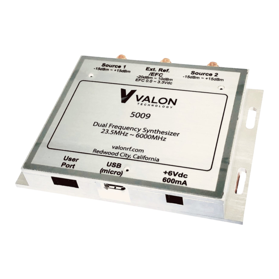
- Page 1 5009 Dual Frequency Synthesizer Module Operations Manual Version 1.36 August 02, 2019 Valon Technology 5009 Operations Manual – Version 1.36 Page 1...
-
Page 2: Table Of Contents
4.4.2 Source <1|2> ........................24 4.4.3 STATus ..........................24 4.4.4 LocK? ............................ 24 4.4.5 ID............................24 4.4.6 Help ............................. 25 4.4.7 RCL ............................25 4.4.8 RST ............................25 4.4.9 SAVe ............................. 25 Valon Technology 5009 Operations Manual – Version 1.36 Page 2... - Page 3 4.9.3 Source <1|2>; OEN <0|1|2 or OFF|ON> ................30 4.9.4 Source <1|2>; PDN <0|1> ....................30 4.9.5 Source <1|2>; AMDepth<0|0.5|1.0|..31.5> ............... 30 4.9.6 Source <1|2>; AMFrequency <f> ..................30 4.10 Configuration Commands ......................31 Valon Technology 5009 Operations Manual – Version 1.36 Page 3...
- Page 4 5.1.1 User Port Pin Assignments ....................34 5.1.2 Lock Detector/Sweep Sync/ Sweep Trigger ................ 34 5.1.3 External Switch and cable recommendations for USER PORT ..........35 Mechanical Dimensions ..........................36 Valon Technology 5009 Operations Manual – Version 1.36 Page 4...
-
Page 5: Introduction
1.2 Detailed Description Figure 1 Block Diagram Figure 1 shows a block diagram of the 5009 system topology. The 32-bit ARM processor controls the operation of the synthesizer as well as storing user settings in non-volatile flash memory. Simple, human readable, commands can be sent through either the micro-USB serial port or to the 3.3V TTL USER port to control the operation of the 5009 synthesizers. - Page 6 The 5009 is equipped with a USER PORT which can be use to provide a direct TTL-serial interface at a default baud rate of 115200. The USER PORT is also used in LIST mode to allow remote Valon Technology 5009 Operations Manual –...
-
Page 7: Electrical Specifications
In SWEEP mode the USER PORT has sweep trigger and sweep enable signals preset. 1.3 Electrical Specifications Note: The 5009 is NOT USB powered See Valon PS6V-1 power supply kit. DC Input Input Voltage Range... - Page 8 -104 -126 -132 -135 -156 -157 dBc/Hz Harmonics The 5009 output waveform is a clipped sine wave. Harmonics are typically 12dBc. Odd harmonics are most prominent. Spurious Non-Harmonic <-60dBc except boundary spurs Output Return loss Min.(dB) Typical(dB) 25~ 100MHz >5 100 ~ 1000MHz >9...
- Page 9 10dB typical 50Ω nominal impedance 10MHz >24dB 20MHz >20dB 50MHz >14dB 100MHz >6dB 200MHz >5dB Pulling range >±10ppm Electronic frequency Control at Voltage ±3V external reference input Input resistance 20kΩ Frequency response 0Hz~>5kHz Valon Technology 5009 Operations Manual – Version 1.36 Page 9...
-
Page 10: User Interface Usb And Ttl User Port
5000term which will connect to the next 5009 synthesizer found. Alternatively, you can type 5000term -S <serial_num> where <serial_num> is the serial number of the 5009. You can find the serial number of the 5009 by using the ID or STATus command. There serial number will appear as shown: Valon Technology, 5009, 12201623, version 1.0... -
Page 11: Setting The Baud Rate
The user is responsible for ensuring the safety of the power source and any components or equipment connected to it including this one. The 5009 can be connected to any number of external components and care should be taken to fully understand the safety issues with these connections. -
Page 12: Power Connections
~600mA maximum (less current if only using one source). The red wire is the positive input and correct polarity is required. The 5009 is reverse polarity protected and no damage will occur if reverse connected to dc power supplies of less than 15V. There is no provision for power to be supplied by USB. -
Page 13: Quick-Start Instructions
Quick-Start Instructions The 5009 Dual Frequency Synthesizer module has been pre-programmed to 2440MHz for the Source1 and 2480MHz for source2. Just apply 6Vdc @ ~600mA using the supplied power cable (red +, black -). Plug it in now! Within 2 seconds, the two blue LED lock lights should be illuminated (see note at end). - Page 14 Figure 3 V5009CM dialog box at program launch. Note that two 5009 synthesizers are shown connected with the option to select either. 4. Once the connection to the synthesizer is established, it is recommended that you select Synthesizer/Read Registers command before you perform any other operation. That will update the Configuration Manager with all the initial register values that were programmed into your synthesizer as it was shipped.
-
Page 15: Configuration Manager (Cm) Graphical User Interface (Gui)
Configuration Manager (CM) graphical user interface (GUI) The Configuration Manager can be used to quickly and easily set the 5009 dual synthesizer frequencies and mode of operation. The Configuration Manager is available as a free download from the Valon Technology Products web site. Install the V5009CM.exe in any directory or on the desktop. -
Page 16: Configuration Manager Main Page
0.0dB turns the modulation off. AM Frequency: The AM frequency range is 0.5Hz to 10kHz. The frequency setting resolution is 1Hz. The AM waveform is 50% duty cycle square wave. Valon Technology 5009 Operations Manual – Version 1.36 Page 16... - Page 17 Reference Trim: Provides ±10ppm trimming range to the internal VCTCXO with 8-bit resolution. Reference Trim is useful when it is desirable to "spot" 5009 frequency to an external frequency when an external reference source is not available. Reference trim can also be used to provide a fine frequency control.
- Page 18 4) Check Reference Frequency setting matches actual internal or external reference frequency in use. 5) Check PFD frequency setting and actual PFD frequency. Figure 4 Default Configuration Manager Main page Valon Technology 5009 Operations Manual – Version 1.36 Page 18...
- Page 19 Figure 5 Configuration Manager Main page after clicking Synthesizer/Read Registers . The Main page is now refreshed with the settings from the connected synthesizer module. Valon Technology 5009 Operations Manual – Version 1.36 Page 19...
-
Page 20: Configuration Manager Sweep Page
CM and will be shown on the Main and List pages as well. Sweep/Start Freq; Set sweep start frequency. Sweep/Stop Freq; Set sweep stop frequency. Sweep/Step Freq; Set sweep step size. Sweep/Rate; Set sweep step rate (milliseconds). Valon Technology 5009 Operations Manual – Version 1.36 Page 20... -
Page 21: Configuration Manager List Page
When the Mode is set to List, the synthesizer presets will be selected by the state of the USER PORT input (see USER PORT for more details). Valon Technology 5009 Operations Manual – Version 1.36 Page 21... -
Page 22: Diagnostics Page
2. Chg (charge) Pump Current. This control change gain of the synthesizers internal loop filter. The default charge pump current is 3. Using other charge pump currents can change the frequency characteristics of the synthesizer's phase noise. Figure 8 Configuration Manager Diagnostic page Valon Technology 5009 Operations Manual – Version 1.36 Page 22... -
Page 23: Programming With A Terminal Program
Once connection to the serial port has been established, type "help" in the teminal program for a list of the latest vailable commands. By convention, the 5009 module is refered to as a dual frequency synthesizer. However in this context, each of the two internal synthsizers will be refered to as a source. -
Page 24: Query Syntax
Source <1|2> 4.4.2 The 5009 contains two independent and identical signal sources. Commands are directed to a particular source by sending the s (select source) command. The select Source command is takes effect for all following commands and it is not necessary to precede any subsequent command or commands with the select source command. -
Page 25: Help
Help 4.4.6 Help list all the commands available for the 5009. Note: Help with commands is not available from the UI. 4.4.7 Recalls the synthesizer state from flash memory. All setting stored in flash memory will be loaded into the synthesizers. This function is useful when it is desirable to restore previously stored flash settings. -
Page 26: Source <1|2>; Mode Sweep
Source 2; Frequency 2000000000 sets source 2 to 2000MHz S 2; f 2000000k sets source 2 to 2000MHz Various valid query forms are accepted For example: Frequency? returns the frequency for the currently selected source. Valon Technology 5009 Operations Manual – Version 1.36 Page 26... -
Page 27: Source <1|2>; Offset
Source2;SWEep;STEp 1 M; Notice in this case the ;SWEep command is required in order to differentiate the sweep step size from the CW increment/decrement step size. Source <1|2>; STARt <F> <U> 4.7.2 Sweep Start frequency. Example: Source2; STARt 2000M Valon Technology 5009 Operations Manual – Version 1.36 Page 27... -
Page 28: Source <1|2; Stop
RetraceTIME ; <ms> 4.7.11 Retrace time or RTIME allows the user to set a dwell interval of 0ms to over 100 seconds before the start of a new sweep. Valon Technology 5009 Operations Manual – Version 1.36 Page 28... -
Page 29: List Mode
See Section 5 User Port for information on hardware control of the List selection. The List selection can either be done with a switch closure to ground or by TTL logic level. Valon Technology 5009 Operations Manual – Version 1.36 Page 29... -
Page 30: Power Level, Attenuation Control, Amplitude Modulation
20dB modulation at 1 kHz the command would be AMD 20. Source <1|2>; AMFrequency <f> 4.9.6 Sets the AM modulation frequency to and value from 1Hz to 10kHz in 1 Hz increments. Valon Technology 5009 Operations Manual – Version 1.36 Page 30... -
Page 31: Configuration Commands
Source <1|2>; PFD <F> <U> 4.10.4 By default, Phase/Frequency Detector (PFD) is 40MHz when the 5009 is supplied with either a 40MHz or 20MHz TCXO. The synthesizer loop filters are optimized for the lowest phase noise with a PFD frequency in the range of 20MHz ~50MHz. A block diagram of the synthesizer reference divider circuit is shown below. -
Page 32: Source <1|2>; Referencedoubler
Reference Doubler to2 using the DEFDB command. Setting the PFD frequency then allows the 5009 to determine the closest R-Divider value that will provide the selected PFD frequency based on the previously set Reference Frequency, Reference Doubler setting, and Reference Divider setting. -
Page 33: Source<1|2>; Sdn<00|10|11
Source<1|2>; NAMe <name> 4.10.10 Allows the user to specify an alias name of up to 48 characters long for each source. Naming the source helps identify the use of each output. Valon Technology 5009 Operations Manual – Version 1.36 Page 33... -
Page 34: User Port
Common ground (same as chassis) The USER PORT mating connector is a Hirose DF11-8DS-2C with pre-terminated cables H3BBT-10112- W4. All available from Digi-Key or you can ordered the 5009 list mode selector switch (LMS-1). Lock Detector/Sweep Sync/ Sweep Trigger 5.1.2 If both sources are in CW mode, pin-7 is the lock detector status output. -
Page 35: External Switch And Cable Recommendations For User Port
In List mode, the 32 preset frequency selection is accomplished by pulling M4:0 USER PORT pins LOW. Figure-8 below shows the schematic of the Valon LSW-1. A 7-conductor cable assembly plugs into the User port and connects to the accessory switch panel. The Phoenix connector provides screw clamping terminal post so that any external switch contact or TTL signal level can also be used if desired. -
Page 36: Mechanical Dimensions
6 Mechanical Dimensions 3.625"W x 2.685"L x 0.55"H Weight: 0.2lbs, 91g Material: AL-6061-T6 Finish: Clear Alodine (conductive) Valon Technology 5009 Operations Manual – Version 1.36 Page 36...
Need help?
Do you have a question about the 5009 and is the answer not in the manual?
Questions and answers