Sony SWF-BR100 Service Manual
Hide thumbs
Also See for SWF-BR100:
- Operating instructions manual (24 pages) ,
- Operating instructions manual (16 pages) ,
- Operating instructions manual (36 pages)
Table of Contents
Advertisement
SERVICE MANUAL
Ver. 1.1 2014.04
• All of the units included in the SWF-BR100 (wire-
less transceiver: UWT-BR100, Audio cable), and
the TV corresponding to SWF-BR100 are required
to confi rming operation of SWF-BR100.
Check in advance that you have all of the units.
Refer to the operating instructions of the SWF-
BR100 or operating instructions of the TV corre-
sponding to SWF-BR100 for the operation method.
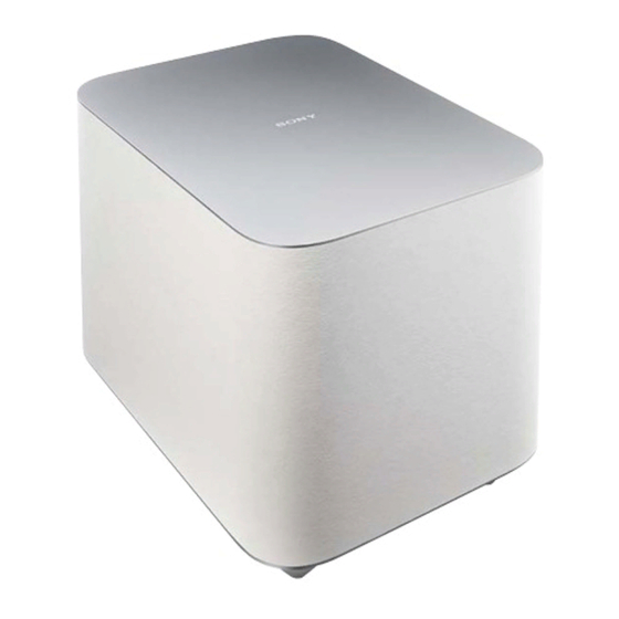
Wireless Subwoofer
(SWF-BR100)
Amplifier section
For U.S.A model:
(FTC)
With 4 ohms load, subwoofer
channel driven, from 30 - 150 Hz;
rated 45 W per channel minimum
RMS power, with no more than 1%
total harmonic distortion from 250
milliwatts to rated output.
POWER OUTPUT (reference)
100 W (per channel at 4 ohms,
100 Hz)
For except US model:
POWER OUTPUT (rated)
70 W (4 ohms, 100 Hz)
(Chinese model)
70 W (4 ohms, 100 Hz, 1% THD)
(Except Chinese model)
POWER OUTPUT (reference)
100 W (4 ohms, 100 Hz)
(Except Chinese model)
Speaker System
Subwoofer, sealed enclosure
Speaker Unit
200 mm cone type
Rated impedance
4 ohms
9-893-941-02
Sony Corporation
2014D33-1
©
2014.04
Published by Sony Techno Create Corporation
SWF-BR100
SPECIFICATIONS
Power requirements
120 V AC, 60 Hz
(US, Canadian and Mexican models)
220V - 240V AC, 50/60 Hz
(UK and Hong Kong models)
240V AC, 50/60 Hz
(Australian and New Zealand models)
220V AC, 50/60 Hz (Chinese model)
110V AC, 50/60 Hz (Taiwan model)
120V - 240V AC, 50/60 Hz (other models)
Power consumption
On: 30W
Standby mode: 0.5W or less
Dimensions (approx.) (w/h/d)
272 mm x 306 mm x 395 mm
10 3/4 in x 12 1/8 in x 15 5/8 in
Mass (approx.)
12.2kg
26 lb 14 3/10 oz
US Model
Canadian Model
AEP Model
UK Model
Australian Model
Chinese Model
Mexican Model
Chilean Model
New Zealand Model
Hong Kong Model
Taiwan Model
Wireless Transceiver
(UWT-BR100)
Communication system
Wireless Sound Specification
version 3.0
Frequency band
5GHz band
(5.180/5.200/5.210/5.240GHz,
5.736/5.762/5.814GHz)
The frequency bands to use are
different by country.
Modulation method
DSSS
Power requirement
5V DC
Power consumption
500 mA
Dimensions (approx.)
19 mm x 27 mm x 91 mm
3/4 in x 1 1/8 in x 3 5/8 in
(w/h/d)
Mass (approx.)
25g
7/8oz
Supplied accessories
Audio cable (1)
Design and specifications are
subject to change without notice.
WIRELESS SUBWOOFER
Advertisement
Table of Contents

Related Manuals for Sony SWF-BR100


Summary of Contents for Sony SWF-BR100
- Page 1 Chilean Model New Zealand Model Hong Kong Model Taiwan Model • All of the units included in the SWF-BR100 (wire- less transceiver: UWT-BR100, Audio cable), and the TV corresponding to SWF-BR100 are required to confi rming operation of SWF-BR100. Check in advance that you have all of the units.
-
Page 2: Table Of Contents
LES DIAGRAMMES SCHÉMATIQUES ET LA LISTE DES PIÈCES SONT CRITIQUES POUR LA SÉCURITÉ DE FONC- TIONNEMENT. NE REMPLACER CES COMPOSANTS QUE PAR DES PIÈCES SONY DONT LES NUMÉROS SONT DON- NÉS DANS CE MANUEL OU DANS LES SUPPLÉMENTS PUBLIÉS PAR SONY. -
Page 3: Servicing Notes
IC pins, etc. ADVANCE PREPARATION WHEN CONFIRMING OP- ERATION All of the units included in the SWF-BR100 (wireless transceiver: UWT-BR100, Audio cable), and the TV corresponding to SWF- BR100 are required to confi rming operation of SWF-BR100. - Page 4 SWF-BR100 Ver. 1.1 MODEL IDENTIFICATION Distinguish by model number label stuck on the rear side of a main unit. Note: The printed contents of following fi gure model number label may be different from the model number label of a main unit.
-
Page 5: Disassembly
SWF-BR100 SECTION 2 DISASSEMBLY • This set can be disassembled in the order shown below. 2-1. DISASSEMBLY FLOW • JIG When disassembling the unit, use the following jig (for speaker removal). Part No. Description J-2501-238-A JIG FOR SPEAKER REMOVAL 2-2. PANEL (COVER) (Page 5) 2-3. -
Page 6: Bottom Plate Block
SWF-BR100 2-3. BOTTOM PLATE BLOCK 6 bottom plate block Note 1: When installing the bottom plate block, align four bosses and four holes. 1 two cushions (foot) 2 two screws 3 boss (BVTP4 2 two screws 1 two cushions (foot) -
Page 7: Loudspeaker (20 Cm) (Sp100)
SWF-BR100 2-4. LOUDSPEAKER (20 cm) (SP100) 2 Remove the loudspeaker (20 cm) (SP100) in the direction of the arrow. 1 eight screws (BVTP4 4 loudspeaker (20 cm) ow to i t e o (SP100) loudspeaker (20 cm) 3 terminal (SP100) -
Page 8: Amp Block
SWF-BR100 2-5. AMP BLOCK 1 cushion Fold the cushion. 2 connector (CN106) Note 2: Please spread a sheet under a unit not to injure top panel. – – 5 AMP block Note 1: When installing the AMP block, refer to “... -
Page 9: How To Install The Amp Block
SWF-BR100 2-6. HOW TO INSTALL THE AMP BLOCK Note 4: Follow the assembly procedure in the numerical order given. AMP block 1 connector (CN105) 2 Pull the wire from the LED board out the rear side. – bottom view –... -
Page 10: Led Board
SWF-BR100 2-7. LED BOARD 1 Insert the jig into the space and slowly remove the panel (back) block. Note 1: When using a jig, please work so as not to injure panel (back) block and speaker cabinet. 2 All bosses are removed while moving jig in the direction of the arrow, and panel (back) block is removed. -
Page 11: Fuse (H.b.c.) (F900)
SWF-BR100 2-8. FUSE (H.B.C.) (F900) 1 six screws 1 six screws (BVTP3 (BVTP3 hole 2 case (top) Note: When installing the case (top), align two ribs and two holes. hole 3 fuse (H.B.C.) (F900) -
Page 12: Rf Modulator (Rf100)
SWF-BR100 2-9. RF MODULATOR (RF100) 5 housing (top) block Note: When installing the flexible flat cable, ensure that the colored line 4 two claws is not slanted after insertion. 4 three claws flexible flat cable 7 RF modulator colored line... -
Page 13: 2-10. Main Board
SWF-BR100 2-10. MAIN BOARD 2-11. POWER CORD (AC1) Note: When the complete MAIN board is replaced, refer to “NOTE OF REPLACING THE IC104 ON THE MAIN BOARD AND THE COMPLETE MAIN BOARD” on page 3. 2 cord bushing (FBS001) 2 two screws... -
Page 14: Diagrams
SWF-BR100 SECTION 3 DIAGRAMS 3-1. BLOCK DIAGRAM RF100 STREAM PROCESSOR POWER AMP RF MODULATOR (WS001) IC105 IC104 WS_DATA_W 31 DATA OUTL1 11 6 PWM_A OUT_C 31 L.P.F. SP100 OUTL2 9 PWM_B OUT_D L.P.F. WS_BCK_W 30 BCK WS_LRCK_W 29 LRCK OUTR1 6... -
Page 15: Printed Wiring Board - Led Board
SWF-BR100 THIS NOTE IS COMMON FOR PRINTED WIRING BOARDS AND SCHEMATIC DIAGRAMS. 3-2. PRINTED WIRING BOARD - LED Board - • : Uses unleaded solder. (In addition to this, the necessary note is printed in each block.) For Printed Wiring Boards. -
Page 16: Printed Wiring Board - Main Board (Side A)
SWF-BR100 3-4. PRINTED WIRING BOARD - MAIN Board (Side A) - • : Uses unleaded solder. POWER BOARD (Page 20) >02P CN901 MAIN BOARD (SIDE A) (CHASSIS) R222 C203 C170 ET100 C178 C200 CL140 C116 CL134 FB102 CN104 D111 CL129... -
Page 17: Printed Wiring Board - Main Board (Side B)
SWF-BR100 3-5. PRINTED WIRING BOARD - MAIN Board (Side B) - • : Uses unleaded solder. MAIN BOARD (SIDE B) JL140 JL144 JL142 JL147 JL174 JL113 JL125 JL171 CL186 JL173 JL172 JL114 JL112 CL187 JL111 JL118 JL151 JL110 JL161 JL108... -
Page 18: Schematic Diagram - Main Board (1/2)
SWF-BR100 3-6. SCHEMATIC DIAGRAM - MAIN Board (1/2) - • See page 22 for Waveforms. • See page 22 for IC Block Diagrams. • See page 26 for IC Pin Function Description. MAIN BOARD (1/2) CL114 R125 C105 0.01 R259... -
Page 19: Schematic Diagram - Main Board (2/2)
SWF-BR100 3-7. SCHEMATIC DIAGRAM - MAIN Board (2/2) - • See page 22 for Waveforms. • See page 22 for IC Block Diagrams. MAIN BOARD (2/2) Q106 HN1A01FU OVER LOAD DETECT CL157 R187 4.7k CL141 JL127 R192 CL154 R200 15.9 15.9... -
Page 20: Printed Wiring Board - Power Board
SWF-BR100 3-8. PRINTED WIRING BOARD - POWER Board - • : Uses unleaded solder. POWER BOARD C914 CL905 D913 CL918 CL912 Q923 D912 CL917 C936 D911 D950 T901 CL914 CL913 SUB POWER R914 CN901 TRANSFORMER C951 CL951 IC910 C919 CL916... -
Page 21: Schematic Diagram - Power Board
SWF-BR100 3-9. SCHEMATIC DIAGRAM - POWER Board - • See page 22 for IC Block Diagrams. POWER BOARD EB901 (CHASSIS) C940 0.0047 CL941 CL942 F900 CN900 T5AH JS903 CL902 250V CL900 (AC IN) R947 R949 C947 LIVE R943 2.2k CL903... - Page 22 SWF-BR100 • Waveforms • IC Block Diagrams IC104 CXD9981TN – MAIN Board – – MAIN Board – IC101 PST8435UL IC111 qa (XOUT) GVDD_B /DTW UNDER- GND 1 VOLTAGE INTERNAL PULLUP PROTECTION RESISTORS TO VREG VREF PROTECTION TEMP. SENSE I/O LOGIC 2.9 Vp-p...
- Page 23 SWF-BR100 IC105 CXD9843AR CLOCK CLOCK GENERATOR GENERATOR 36 XFSIIN (SECONDARY) (PRIMARY) XVSS 35 DVDD VSUBC 34 TEST 33 BFVSS VSSR OUTR2 32 BFVDD VDDR DATA FILTER & SAMPLING OUTR1 LINER GAIN LOW CUT RATE S g P INTERPOLATOR CONTROL VSSR...
- Page 24 SWF-BR100 IC108 S-1170B33UC-OTSTFG IC109 SI-3010KM-TLA VOUT OVERCURRENT PROTECTION THERMAL SHUTDOWN ON/OFF ON/OFF CONTROL – – REFERENCE VOLTAGE VOUT – POWER Board – IC910 STR-A6159M BUFFER – FEED OVER BACK SOURCE/OCP CURRENT PROTECTION BLANKING BURST DISCHARGE BIAS OFF TIMER LATCH OVER LOAD...
- Page 25 SWF-BR100 IC920 STR-W6765N DRIVE REGULATOR REGULATOR PROTECTION START/STOP & ICONST – LATCH BURST DELAY BURST CONTROL NC 2 S/GND 3 VCC 4 SS/OLP 5 – SOFT START FB 6 – – – BOTTOM SELECTOR COUNTER – OCP/BD 7...
- Page 26 SWF-BR100 • IC Pin Function Description MAIN BOARD IC111 R5F3650ECDFB (SYSTEM CONTROLLER) Pin No. Pin Name Description 1 to 5 Not used BYTE External data bus width selection signal input terminal Fixed at “L” in this unit CNVSS Processor mode selection signal input terminal...
- Page 27 SWF-BR100 Pin No. Pin Name Description WS_GPIO2 (INT) S-AIR interrupt signal input from the RF modulator WS_RESET S-AIR reset signal output to the RF modulator “L”: reset !INT5! Not used KEY_PW Power key input terminal KEY_PAIR SECURE key input terminal...
-
Page 28: Exploded Views
SWF-BR100 Ver. 1.1 SECTION 4 EXPLODED VIEWS Note: • -XX and -X mean standardized parts, so • The mechanical parts with no reference The components identifi ed by mark 0 they may have some difference from the number in the exploded views are not sup- or dotted line with mark 0 are critical for original one. -
Page 29: Panel Section
SWF-BR100 Ver. 1.1 4-2. PANEL SECTION not supplied SP100 not supplied module section Ref. No. Part No. Description Remark Ref. No. Part No. Description Remark 4-484-889-01 PANEL (BACK) (for WHITE) (Except Chinese) A-1979-005-A LED BOARD, COMPLETE 4-484-889-11 PANEL (BACK) (for WHITE) (Chinese) -
Page 30: Module Section
SWF-BR100 Ver. 1.1 4-3. MODULE SECTION not supplied board section not supplied not supplied FFC1 not supplied RF100 not supplied not supplied not supplied not supplied Ref. No. Part No. Description Remark Ref. No. Part No. Description Remark FFC1 9-833-606-22 WIRE KIT (Flexible fl... -
Page 31: Board Section
SWF-BR100 4-4. BOARD SECTION not supplied F900 not supplied Note: When the complete MAIN board is replaced, refer to “NOTE OF REPLACING THE IC104 ON THE MAIN BOARD AND THE COMPLETE MAIN BOARD” on page 3. Ref. No. Part No. -
Page 32: Electrical Parts List
SWF-BR100 SECTION 5 MAIN ELECTRICAL PARTS LIST Note: • Due to standardization, replacements in • CAPACITORS The components identifi ed by mark 0 the parts list may be different from the uF: μF or dotted line with mark 0 are critical for parts specifi... - Page 33 < DIODE > R130 1-218-965-11 METAL CHIP 1/16W D101 6-502-961-01 DIODE DA2J10100L R146 1-216-841-11 METAL CHIP 1/10W D111 6-503-775-01 DIODE CRH02 (T5R, SONY, XM) R147 1-216-833-11 METAL CHIP 1/10W D112 6-502-966-01 DIODE DZ2J056M0L R148 1-218-961-11 METAL CHIP 4.7K 1/16W R149...
- Page 34 SWF-BR100 MAIN POWER Ref. No. Part No. Description Remark Ref. No. Part No. Description Remark R202 1-216-845-11 METAL CHIP 100K 1/10W 0 C921 1-116-393-21 FILM 0.0033uF 400V R203 1-216-845-11 METAL CHIP 100K 1/10W 0 C922 1-125-893-11 FILM 680PF 1.5KV R205...
- Page 35 SWF-BR100 Ver. 1.1 POWER Ref. No. Part No. Description Remark Ref. No. Part No. Description Remark < FUSIBLE RESISTOR > R946 1-250-650-11 METAL CHIP 1/10W R947 1-216-825-11 METAL CHIP 2.2K 1/10W 0 FR910 1-246-373-11 FUSIBLE 1/2W R949 1-216-821-11 METAL CHIP...
- Page 36 SWF-BR100 Ver. 1.1 Ref. No. Part No. Description Remark ACCESSORIES ************ 4-488-516-41 MANUAL, INSTRUCTION (JAPANESE, ENGLISH, FRENCH, SPANISH, PORTUGUESE) (US, Canadian, Mexican) 4-488-516-61 MANUAL, INSTRUCTION (ENGLISH, SIMPLIFIED CHINESE, TRADITIONAL CHINESE, VIETNAMESE) (AEP, Russian, UK, Australian, Chinese, Chilean, New Zealand, Hong Kong, Taiwan)
- Page 37 SWF-BR100 US Model Canadian Model SERVICE MANUAL AEP Model UK Model Australian Model Ver. 1.1 2014.04 Chinese Model Mexican Model Chilean Model New Zealand Model Hong Kong Model Taiwan Model SUPPLEMENT-1 File this supplement with the service manual. File this supplement with the service manual.
- Page 38 SWF-BR100 TROUBLESHOOTING Flow of symptom check, operation check Wireless Transceiver (UWT-BR100) Potential symptom: No sound, intermittent sound, noise, strange sound. Note: Please check it without less RF interferences. Please connect Wireless Transceiver (UWT-BR100) to PC, if there is no TV. Please refer to the technical information (DI-Net: DIG0003217) issued separately for how to use PC.
- Page 39 SWF-BR100 Flow of subwoofer internal analysis: POWER board Defect is There is no defective (harness exist Repair the harness or replace floating, come out contact pin, the harness. pin bent etc.) to harness connecting on the CN104 on the MAIN board and CN901 on the POWER board.
- Page 40 SWF-BR100 Flow of subwoofer internal analysis: MAIN board The voltages of pins of the each power IC on the MAIN Replace the each power IC board is the following value. on the MAIN board. MAIN board: Repair or replace the harness...
- Page 41 SWF-BR100 MEMO...
- Page 42 SWF-BR100 REVISION HISTORY Ver. Date Description of Revision 2014.01 2014.04 Addition of BLACK color type (US, Canadian, AEP, Russian, Chilean and Mexican models) Change of Part No. for MODEL NUMBER LABEL (AEP, Russian and Chilean models) (for White) Change of SCREW (Ref. No. #1 t #2) Change of Part No.
Need help?
Do you have a question about the SWF-BR100 and is the answer not in the manual?
Questions and answers