Table of Contents
Advertisement
Quick Links
®
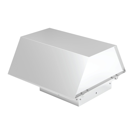
This publication contains the installation, operation and
maintenance instructions for standard units of the LC (HLC-D,
HLC-B, TLC-D and TLC-B): Low Profile Roof Exhausters.
Carefully read this publication and any
supplemental documents prior to any
installation or maintenance procedure.
Loren Cook catalog, LC, provides additional information de-
scribing the equipment, fan performance, available accesso-
ries and specification data.
For additional safety information, refer to AMCA Publication
410-96, Safety Practices for Users and Installers of Industrial
and Commercial Fans.
All of the publications listed above can be obtained from:
• lorencook.com
• info@lorencook.com
• 417-869-6474 ext. 166
For information and instructions on special equipment, con-
tact Loren Cook Company at 417-869-6474.
Receiving and Inspection
Carefully inspect the fan and accessories for any damage
and shortage immediately upon receipt of the fan.
• Turn the wheel by hand to ensure it turns freely and does
not bind
• Check dampers (if included) for free operation of all mov-
ing parts
• Record on the Delivery Receipt any visible sign of damage
Handling
Lift the fan by the base or the shipping carton.
NOTICE! Never lift by the shaft, motor or housing.
Storage
If the fan is stored for any length of time prior to installation,
completely fill the bearings with grease or moisture-inhibiting oil
(refer to Fan Bearing, page 4). Store the fan in its original crate
and protect it from dust, debris and weather.
• Cover the inlet, and outlet opening to prevent the accumula-
tion of dirt and moisture in the housing
• Periodically rotate the wheel and operate to keep a coating
of grease on all internal bearing parts
• Periodically inspect the unit to prevent damaging conditions
LC IO&M
INSTALLATION, OPERATION AND MAINTENANCE MANUAL
HLC
1
Rotating Parts & Electrical Shock Hazard:
Fans should be installed and serviced by qualified personnel
only.
Disconnect electric power before working on unit (prior to re-
moval of guards or entry into access doors).
Follow proper lockout/tagout procedures to ensure the unit
cannot be energized while being installed or serviced.
A disconnect switch should be placed near the fan in order
that the power can be swiftly cut off, in case of an emergency
and in order that maintenance personnel are provided com-
plete control of the power source.
Grounding is required. All field-installed wiring must be com-
pleted by qualified personnel. All field installed wiring must
comply with National Electric Code (NFPA 70) and all appli-
cable local codes.
Fans and blowers create pressure at the discharge and vac-
uum at the inlet. This may cause objects to get pulled into the
unit and objects to be propelled rapidly from the discharge.
The discharge should always be directed in a safe direction
and inlets should not be left unguarded. Any object pulled into
the inlet will become a projectile capable of causing serious
injury or death.
When air is allowed to move through a non-powered fan, the
impeller can rotate, which is referred to as windmilling. Wind-
milling will cause hazardous conditions due to unexpected ro-
tation of components. Impellers should be blocked in position
or air passages blocked to prevent draft when working on fans.
Friction and power loss inside rotating components will cause
them to be a potential burn hazard. All components should be
approached with caution and/or allowed to cool before con-
tacting them for maintenance.
Under certain lighting conditions, rotating components may
appear stationary. Components should be verified to be sta-
tionary in a safe manner, before they come into contact with
personnel, tools or clothing.
Failure to follow these instructions could result in death or se-
rious injury.
The attachment of roof mounted fans to the roof curb as well
as the attachment of roof curbs to the building structure must
exceed the structural requirements based on the environmen-
tal loading derived from the applicable building code for the
site. The local code official may require variations from the
recognized code based on local data. The licensed engineer
of record will be responsible for prescribing the correct attach-
ment based on construction materials, code requirements and
environmental effects specific to the installation.
LC
Low Profile Roof Exhausters
B51031-004
Advertisement
Table of Contents

Subscribe to Our Youtube Channel
Summary of Contents for LC COOK HLC-D
- Page 1 INSTALLATION, OPERATION AND MAINTENANCE MANUAL ® This publication contains the installation, operation and maintenance instructions for standard units of the LC (HLC-D, HLC-B, TLC-D and TLC-B): Low Profile Roof Exhausters. Rotating Parts & Electrical Shock Hazard: Carefully read this publication and any...
-
Page 2: Pulley Alignment
It is Up through 12” 1/16” 12” up through 48” 1/8” possible to interchange two leads at this location so Over 48” 1/4” that the fan is operating in the correct direction. CENTER Figure 2 DISTANCE (CD) LC IO&M B51031-004... -
Page 3: Wiring Diagrams
1920 Motor Motor 7/16 7/32” 1”-8 2700 1/4” 1-1/8”-7 4200 Open Line 5/16” 1120 1280 1-1/4”-7 6000 3/8” 1680 1920 1/2” 4200 4800 To reverse, interchange any two line leads. Motors require magnetic 9/16” 5600 6400 control. LC IO&M B51031-004... -
Page 4: Maintenance
< -30 Consult Factory Chevron SRI. Any Speed > 200 1/2 week The above intervals should be reduced to half for vertical For moist or otherwise contaminated installations, divide the shaft installations. interval by a factor of three. LC IO&M B51031-004... - Page 5 Adjust the overlap by loosening the wheel hub and moving 8. Install the belts on the pulleys. Align and adjust the belts the wheel along the shaft to obtain the correct value. to the proper tension as described in Belt and Pulley In- stallation, page 2. LC IO&M B51031-004...
-
Page 6: Troubleshooting
• Cooling air diverted or blocked • Improper inlet clearance • Incorrect fan RPMs • Incorrect Voltage Overheated Bearings: • Improper bearing lubrication • Excessive belt tension LC IO&M B51031-004... -
Page 7: Parts List
Hood Assembly Birdscreen Assembly Hood Support (2) Hood Support (2) Power Assembly Rail (2) Driver Sheave Driver Sheave Birdscreen Assembly Birdscreen Assembly Belt Set Belt Set Driven Sheave Driven Sheave Power Assembly Rail (2) Power Assembly Rail (2) LC IO&M B51031-004... -
Page 8: Limited Warranty
Loren Cook Company will not be responsible for any removal or installation costs. Corporate Offices: 2015 E. Dale St. Springfield, MO 65803 Phone 417-869-6474 | Fax 417-862-3820 | lorencook.com September 2020 LC IO&M B51031-004...
Need help?
Do you have a question about the COOK HLC-D and is the answer not in the manual?
Questions and answers