
Summary of Contents for Force Technology FiGS 2.0
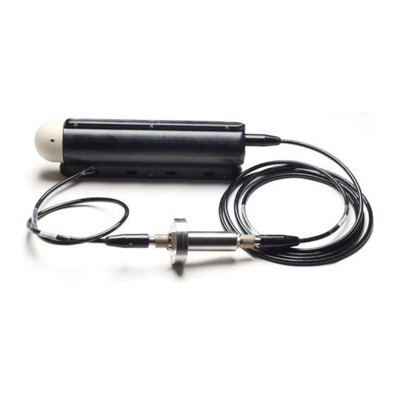
- Page 1 FiGS 2.0 Sensor and Power bottle User / Service Manual / Quick Guide Sensor for measurement of electric field gradients in seawater...
- Page 2 Manual Nov. 2020 ver. 2 – English This manual exists in electronic (PDF) and printed format.
- Page 3 Contact information FORCE Technology Norway AS Hornebergveien 1 7038 Trondheim Norway Phone : 64005000 Email : figs@force.no Abbreviations FTN: FORCE Technology Norway AS...
- Page 4 FiGS 2.0 has been tested and found to comply with the limits for a Class B digital device, pursuant to Part 15 of the FCC Rules. These limits are designed to provide reasonable protection against harmful interference in a residential installation.
- Page 5 Important Safety and Handling Information Caution: Changes/modifications not approved by FORCE Technology could void the user’s authority to operate the equipment. Disposal and Recycling Information Please ask FORCE Technology concerning disposal of FiGS 2.0 in your country.
- Page 6 Disclaimer The information contained in this document is subject to change without notice. FORCE TECHNOLOGY NORWAY AS MAKES NO WARRANTY OF ANY KIND WITH REGARD TO THIS MATERIAL, INCLUDING, BUT NOT LIMITED TO, THE IMPLIED WARRANTIES OF MERCHANTABILITY AND FITNESS FOR A PARTICULAR PURPOSE. FORCE TECHNOLOGY NORWAY AS SHALL NOT BE LIABLE FOR ERRORS CONTAINED HEREIN OR FOR INCIDENTAL OR CONSEQUENTIAL DAMAGES IN CONNECTION WITH THE FURNISHING, PERFORMANCE OR USE OF THIS MATERIAL.
-
Page 7: Table Of Contents
Contents Intended use of the equipment ........................ 8 FiGS 2.0 usage ............................ 8 What does FiGS 2.0 measure ........................ 8 Overview of the sensor ........................8 Sensor dimensions ..........................10 Power bottle dimension ........................10 Equipment ratings ..........................11 FiGS 2.0 sensor: ..........................11 FiGS 2.0 Power bottle: ........................ -
Page 8: Intended Use Of The Equipment
FiGS 2.0 usage FiGS 2.0 is a sensor for measurement of cathodic protection activity and corrosion for assets in seawater, such as pipelines, subsea structures and fixed installations. - Page 9 The sensor consists of 3 main parts: Rotor Motor housing Electronics housing The sensor is built up with 3 sensing electrodes mounted on a rotating shaft. The rotating part, from now on called the rotor, will rotate at a speed of 250 or 500RPM when the sensor is in operation. The motor and part of the rotor is enclosed in the motor housing, which is oil filled and pressure compensated.
-
Page 10: Sensor Dimensions
Sensor dimensions All dimensions are in [mm] Power bottle dimension... -
Page 11: Equipment Ratings
Equipment ratings FiGS 2.0 sensor: Supply voltage: 24VDC Supply current: Maximum power consumption: Typical power consumption: Over Voltage Category Data connection: RS 485 full duplex Connector spec: Transmark TS-FCR-08P-MING-3S Temperature: -15 / +50C Pressure 3000MSW / 300barg Matings +500 Isolation... -
Page 12: Figs 2.0 Power Bottle
FiGS 2.0 Power bottle: Supply voltage: 21-27VDC Supply current, full load: 3.4A Output Voltage 24VDC Output current: Over Voltage Category Volts, transient, 100 mSec 0-50VDC Maximum power consumption: Data connection sensor side: RS 485 full duplex Data connection computer side:... -
Page 13: Equipment Installation
Equipment installation Connect FiGS 2.0 sensor to the FiGS 2.0 power bottle with the supplied cable. Check that the power bottle is mounted the correct way. The power bottle is marked with “FiGS side” and “ROV side” on the bottle. If the power bottle is mounted the wrong way, the sensor will fail to power up. -
Page 14: Equipment Operation
Connect the sensor to the computer via the RS232 interface. The sensor can be controlled by a terminal software, such as Putty, or by a specific logging and control software. Protocol FiGS 2.0 FiGS can communicate over RS-232 at 19200, 115800 and 1000000 baud. The communication is ASCI based, i.e. -
Page 15: Non-Formatted Messages
messages easier to read in a terminal window. NB! (\n) cannot be used as a terminal character when reading from the serial port. Non-formatted messages In addition to the formatted messages, FiGS also prints loose text. This is intended to be read by humans and should not be parsed by a computer. -
Page 16: System
{SYSTEM} System contains the following parameters, separated by tab (\t) or newline (\n) id: 1835060 A unique number identifying the master processor digital filter: 1 System settings for digital filter (50Hz Cut-off). 0 is off, 1 is on digital AC: 1 System settings for digital AC filter. -
Page 17: R Stat
auto gain lower: 6 auto gain lower limit auto gain upper: 85 auto gain upper limit auto gain enabled: 1 auto gain, 0 is deactivated, 1 is active master version: 0.9.2 Master software version {R STAT} {R STAT} contains the following parameters, separated by tab (\t) or newline (\n) id: 4653098 A unique number identifying the rotor processor hum: 31.12... -
Page 18: Vector
24 volt: 23.68 24 volt value target rpm: 0 target motor speed actual rpm: 0.00 actual motor speed average rpm: 0.00 average motor speed std rpm: 0.00 standard deviation motor speed min rpm: 0.00 minimum motor speed max rpm: 0.00 maximum motor speed throttle: 0 throttle... -
Page 19: Haldmp
-336.620497 -336.620268 -336.620156 -336.619807 -336.619441 {HALDMP} {HALDMP} contains hall sensor samples. {HALDMP} contains the following parameters separated by tab (\t) H1raw: 1305 Sample from hall sensor 1 H2raw: 2029 Sample from hall sensor 2 Commands The following commands are available. A command always starts with ‘#’ Arguments are called with commas in between as in the example below: #set motor speed,250<ENTER>... -
Page 20: How To Send Commands
set pt filter - 1 arg: 1 220nf cap in pipetracker filter, 0 for 10nf set filter - 1 arg: 1 for cutoff at 50hz, 0 for cutoff at 500hz set gain - 1 arg: 1 for high gain (100), 0 for low gain (10) mute vectors - 1 arg: 1 mutes vectors, 0 unmutes them mute status... - Page 21 complete string. This is because the sensor at the same time writes the characters back to the console. It is recommended to use a 1ms delay between each character written.
-
Page 22: Instructions For Interconnection To Accessories And Other Equipment, Including Indication Of Suitable Accessories, Detachable Parts And Any Special Materials
Instructions for interconnection to accessories and other equipment, including indication of suitable accessories, detachable parts and any special materials The nonmetallic bracket which is delivered with the sensor can be replaced with a custom bracket if needed. Contact FTN for options. A sliding rail with quick connection is available for the bracket. -
Page 23: Explanations Of Symbols Related To Safety Which Are Used On The Equipment
Explanations of symbols related to safety which are used on the equipment Serial number CE mark – indicates conformance with the essential requirements of the directive ##NAME OF DIRECTIVE Dispose of the instrument in compliance with local regulations for the disposal of electronic equipment. -
Page 29: Maintenance
MAINTENANCE Cleaning After every use. To clean the sensor, perform the following steps: 1. Keep the cables connected to the receptables or us a dummy-connector to keep the receptable pins dry. Clean the sensor in cold freshwater. Use a hose to hose off any seawater and salt remnants. Dry off with paper towels or leave to dry. -
Page 30: Regular Maintenance
Sensor head Electrode 4. For special cleaning, skip part 3 and place the sensor head in an ultrasonic bath with isopropyl alcohol for 2 minutes. Leave to dry and mount new cotton plugs and remount the electrode caps. 5. Cleaning of receptables: remove connector and O-rings and clean the receptable with a soft cloth soaked in isopropyl alcohol. - Page 31 o Oil-fill plug on motor housing Oil-fill plug o Oil-fill plug on penetrator Oil-fill plug o Around oil-filled hose...
- Page 32 Oil filled hose o Between motor housing and electronics housing Check for oil 2. Check for damage to cables and connectors. Any damaged cable must be replaced. Failure to replace damaged cables can result in damage to the sensor and loss of function of the sensor. Contact FTN for replacement cables.
-
Page 33: Integration Into Systems
Warning! Do not replace bolts! The bolts are made specifically for this sensor. Replacement of bolts made from other materials and /or other specifications may lead to water ingress and erroneous measurements. Replacement bolts can be obtained from FTN. Note: If any leakage is found, contact FTN for service. Unrepaired leakages will result in loss of oil and possibly loss of function of the sensor. -
Page 34: Label / Marking For Model Identification
Label / Marking for model identification The sensor and power bottle are marked with the following tags and symbols. On Sensor On Power bottle...
Need help?
Do you have a question about the FiGS 2.0 and is the answer not in the manual?
Questions and answers